A transformer short-circuit fault location detection method and system
A short-circuit fault and location detection technology, which is applied in transformer testing, short-circuit testing, electric/magnetic solid deformation measurement, etc., can solve problems such as inability to locate short-circuit faults, and achieve the effect of preventing power grid accidents
- Summary
- Abstract
- Description
- Claims
- Application Information
AI Technical Summary
Problems solved by technology
Method used
Image
Examples
Embodiment 1
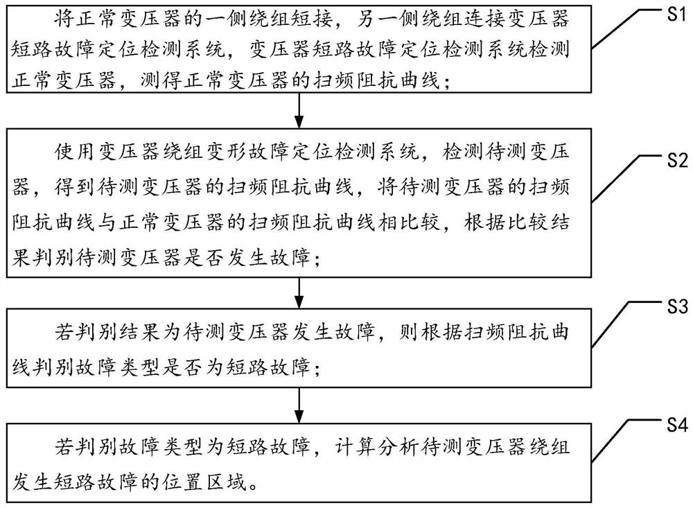
[0054] see figure 1 , figure 1 It is a flow chart of a transformer short-circuit fault location and detection method and system provided by an embodiment of the present invention.
[0055] A transformer short-circuit fault location detection method provided by the present invention is suitable for a pre-established transformer short-circuit fault location detection system, and the method includes the following steps:
[0056] Step S1: short-circuit the winding on one side of the normal transformer, and connect the winding on the other side to the transformer short-circuit fault location detection system, use the transformer short-circuit fault location detection system to detect the normal transformer, and measure the short-circuit impedance in a specific frequency band (10hz-1Mhz), Draw the frequency sweep impedance curve of the normal transformer according to the frequency change and impedance value;
[0057] Step S2: Use the transformer short-circuit fault location detect...
Embodiment 2
[0074] This embodiment provides a transformer short-circuit fault location detection system, including a signal generator, a power amplifier, a data acquisition card and a microprocessor, and the microprocessor is respectively connected to the input end of the signal generator and the output end of the data acquisition card The output terminal of the signal generator is connected with the input terminal of the power amplifier.
[0075] Further, the working process of the transformer short-circuit fault location detection system is explained. The signal generator of the transformer short-circuit fault location detection system sends out a sinusoidal signal of 10 Hz to 1 MHz, and the sinusoidal signal is transmitted to the power amplifier. Carry out signal amplification, and apply the amplified signal to the transformer winding, the data acquisition card collects the voltage and current in the transformer winding, and transmits the data of voltage and current to the microprocesso...
Embodiment 3
[0077] In this embodiment, it is specifically described how the transformer winding deformation fault location detection system solves the frequency sweep impedance;
[0078] Short-circuit the outgoing line of the high-voltage side or low-voltage side of the transformer, and load the frequency sweep signal at the first end of the non-short-circuit side winding After the signal passes through the winding, the output signal at the end of the winding is obtained by using the grounding resistor R According to the above data, the frequency sweep impedance value of the transformer can be obtained as:
[0079]
[0080] in To detect the current, ω is the angular frequency of the injected signal; R is the resistance of the transformer; X is the reactance of the transformer.
[0081] Thus, the frequency sweep impedance value can be obtained as:
[0082]
[0083] Since the nameplate value of the transformer is generally represented by impedance voltage, the frequency sweep im...
PUM
 Abstract
Description
Claims
Application Information
 - R&D
- Intellectual Property
- Life Sciences
- Materials
- Tech Scout
- Unparalleled Data Quality
- Higher Quality Content
- 60% Fewer Hallucinations
Browse by: Latest US Patents, China's latest patents, Technical Efficacy Thesaurus, Application Domain, Technology Topic, Popular Technical Reports.
© 2025 PatSnap. All rights reserved.Legal|Privacy policy|Modern Slavery Act Transparency Statement|Sitemap|About US| Contact US: help@patsnap.com


