Long-focus optical imaging system and zoom imaging apparatus

An optical imaging system, telephoto technology, applied in optics, optical components, instruments, etc., can solve the problems of optical characteristics limitation, limited effect, complicated and difficult problems of telephoto optical imaging system, and reduce the loss of light energy and structure. Simple, large zoom range effects

Active Publication Date: 2020-04-17
ZHEJIANG SUNNY OPTICAL CO LTD
View PDF11 Cites 3 Cited by
  • Summary
  • Abstract
  • Description
  • Claims
  • Application Information

AI Technical Summary

Problems solved by technology

The increase in the number of lenses in the optical imaging system makes both the optimization in the early stage and the manufacturing in the later stage more complicated and difficult
On the other hand, the mobile phone industry tends to adopt multiple sets of optical imaging systems for multi-camera. The multiple sets of optical imaging systems highlight different optical characteristics, which usually include a telephoto optical imaging system with a longer focal length. Due to the thickness of the mobile phone The limitations of the optical characteristics of the telephoto optical imaging system are limited, which limits the imaging effects of mobile phones such as background blur and object magnification.

Method used


Image

  • Long-focus optical imaging system and zoom imaging apparatus
  • Long-focus optical imaging system and zoom imaging apparatus
  • Long-focus optical imaging system and zoom imaging apparatus

Examples


Embodiment 1

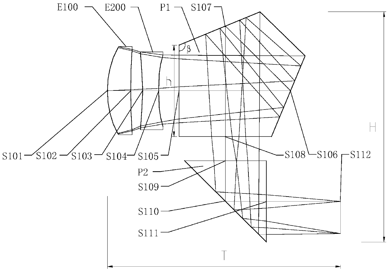
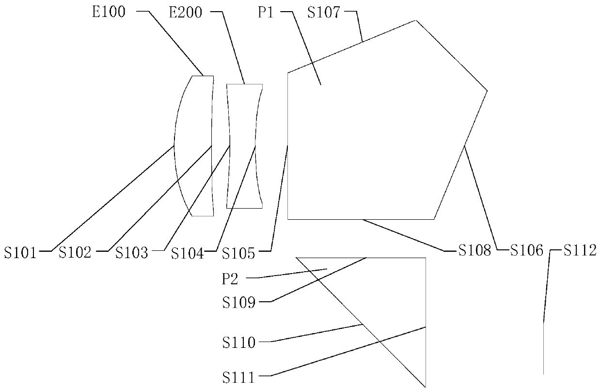
[0060] Refer to the following Figure 2 to Figure 3D A telephoto optical imaging system according to Embodiment 1 of the present application will be described. figure 2 A schematic structural diagram of a telephoto optical imaging system according to Embodiment 1 of the present application is shown.

[0061] Such as figure 2 As shown, the telephoto optical imaging system includes in sequence from the object side to the image side along the optical axis: a first lens E100 , a second lens E200 , a folding prism P1 and a triangular prism P2 .

[0062] The first lens E100 has positive refractive power, its object side S101 is convex, and its image side S102 is concave. The second lens has negative refractive power, its object side S103 is concave, and its image side S104 is concave. The incident surface S105 of the folding prism P1 to the outgoing surface S111 of the triangular prism P2 are all spherical surfaces with an infinite radius. The light from the object passes thro...

Embodiment 2

[0075] Refer to the following Figure 4 to Figure 5D A telephoto optical imaging system according to Embodiment 2 of the present application will be described. In this embodiment and the following embodiments, for the sake of brevity, descriptions similar to those in Embodiment 1 will be omitted. Figure 4 A schematic structural diagram of a telephoto optical imaging system according to Embodiment 2 of the present application is shown.

[0076] Such as Figure 4 As shown, the telephoto optical imaging system includes in sequence from the object side to the image side along the optical axis: a first lens E100 , a second lens E200 , a folding prism P1 and a triangular prism P2 .

[0077] The first lens E100 has positive refractive power, its object side S101 is convex, and its image side S102 is concave. The second lens has negative refractive power, its object side S103 is concave, and its image side S104 is concave. The incident surface S105 of the folding prism P1 to the ...

Embodiment 3

[0086] Refer to the following Figure 6 to Figure 7D A telephoto optical imaging system according to Embodiment 3 of the present application is described. Figure 6 A schematic structural diagram of a telephoto optical imaging system according to Embodiment 3 of the present application is shown.

[0087] Such as Figure 6 As shown, the telephoto optical imaging system includes in sequence from the object side to the image side along the optical axis: a first lens E100 , a second lens E200 , a folding prism P1 and a triangular prism P2 .

[0088] The first lens E100 has positive refractive power, its object side S101 is convex, and its image side S102 is concave. The second lens has negative refractive power, its object side S103 is concave, and its image side S104 is concave. The incident surface S105 of the folding prism P1 to the outgoing surface S111 of the triangular prism P2 are all spherical surfaces with an infinite radius. The light from the object passes through t...


PUM


Abstract

The invention discloses a long-focus optical imaging system and a zoom imaging apparatus. The long-focus optical imaging system sequentially comprises a first lens with positive focal power, a secondlens with negative focal power, a turn-back prism and a triangular prism from an object side to an image side along an optical axis. The incident surface of the turn-back prism is perpendicular to theaxis of the second lens, the emergent surface of the turn-back prism is perpendicular to the incident surface of the turn-back prism, and imaging light entering the turn-back prism along the opticalaxis is sequentially reflected at a first turn-back surface of the turn-back prism and a second turn-back surface of the turn-back prism and is perpendicularly emitted out from the emergent surface ofthe turn-back prism. The light vertically emitted from the emergent surface of the turn-back prism is reflected at the reflecting surface of the triangular prism and deflects by 90 degrees, and the deflection direction faces the image side. At least one aspheric lens surface is arranged between the object side surface of the first lens and the image side surface of the second lens. The total effective focal length F1 of the long-focus optical imaging system meets the condition that F1 is larger than 40 mm.

Description

technical field [0001] The present application relates to the field of optical elements, and more specifically, to a telephoto optical imaging system and a zoom camera device. Background technique [0002] At present, the requirements for imaging functions of portable electronic devices are getting higher and higher, and the camera devices of mobile phones are developing in the direction of high resolution, large field of view, light weight and multifunctionality. This requires the optical imaging system in the camera device to have multiple characteristics such as large aperture, long focal length, wide field of view, compact structure, high image quality and low distortion. And since the portable electronic device is expected to have a smaller size, the size of the optical imaging system provided thereon is also limited. [0003] Faced with these high requirements, on the one hand, the optical imaging system of the mobile phone camera device is becoming more and more comp...

Claims


Application Information

Patent Timeline
Patent Type & Authority Applications(China)
IPC IPC(8): G02B13/00
CPCG02B13/003G02B13/0065G02B13/0045G02B15/1421G02B13/02G02B15/1461G02B17/004G02B17/0896
Inventor 戴付建张凯元赵烈烽
Owner ZHEJIANG SUNNY OPTICAL CO LTD
Why Eureka
Try Eureka