
Method, device and system for automatically generating equipment control interface

A device control and automatic generation technology, applied in the direction of program control device, user interface execution, image data processing, etc., can solve the problems of long cycle and high development cost, achieve the effect of convenient management and control, and reduce operation errors

Active Publication Date: 2020-04-17
GREE ELECTRIC APPLIANCES INC OF ZHUHAI
View PDF5 Cites 0 Cited by
  • Summary
  • Abstract
  • Description
  • Claims
  • Application Information

AI Technical Summary

Problems solved by technology

[0005] Embodiments of the present invention provide a method, device and system for automatically generating a device control interface to solve the problems of high development costs and long development cycles of terminal device control systems in the prior art

Method used


Image

  • Method, device and system for automatically generating equipment control interface
  • Method, device and system for automatically generating equipment control interface
  • Method, device and system for automatically generating equipment control interface

Examples


Embodiment 1

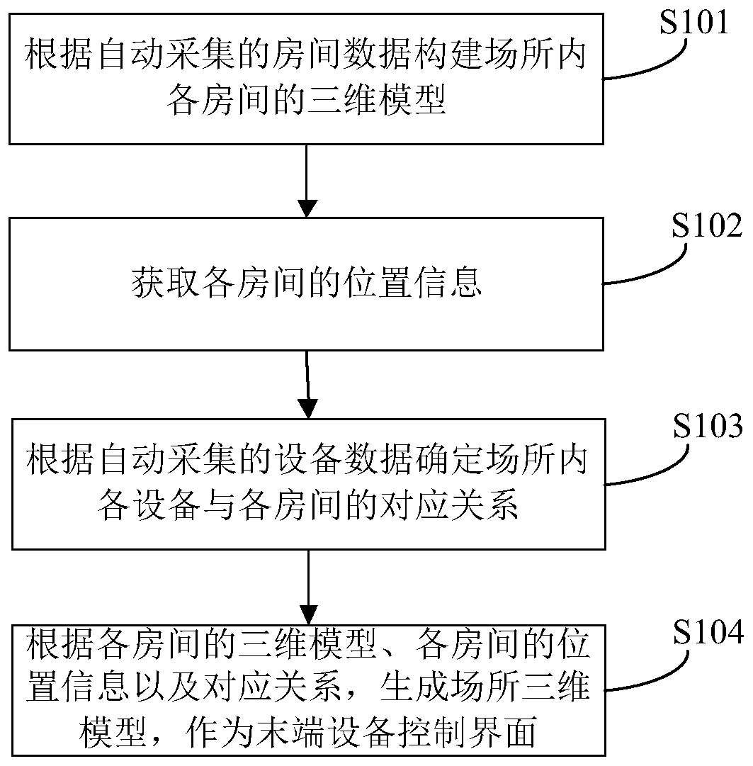
[0022] This embodiment provides a method for automatically generating a device control interface, which can be used to automatically generate a device control interface that is easy to operate and has a friendly interface, and reduces the development cost and cycle of the device control system. The equipment can be an end device in a refrigeration unit or a heating unit. figure 1 It is a flowchart of a method for automatically generating a device control interface provided in the first embodiment of the present invention, such as figure 1 As shown, the method includes the following steps:

[0023] S101: Construct a three-dimensional model of each room in the site according to automatically collected room data.

[0024] S102: Acquire location information of each room.

[0025] S103: Determine the correspondence between each device in the place and each room according to the automatically collected device data.

[0026] S104, according to the three-dimensional model of each room, the lo...

Embodiment 2

[0045] Based on the same inventive concept, this embodiment provides an apparatus for automatically generating a device control interface, which can be used to implement the method for automatically generating a device control interface described in the foregoing embodiment. The device may be implemented by software and / or hardware, and the device may generally be integrated in a terminal, for example, a control terminal of a device.

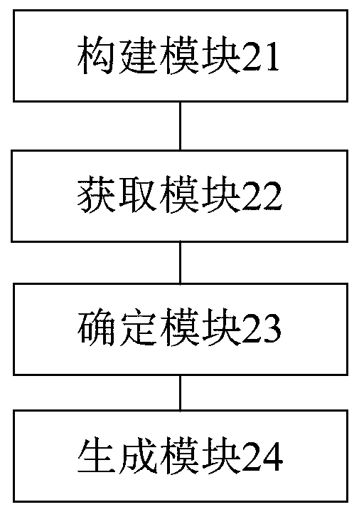
[0046] figure 2 It is the structural block diagram of the device for automatically generating the device control interface provided in the second embodiment of the present invention, such as figure 2 As shown, the device includes:

[0047] The construction module 21 is used to construct a three-dimensional model of each room in the place according to the automatically collected room data;

[0048] The obtaining module 22 is used to obtain location information of each room;

[0049] The determining module 23 is used to determine the correspondence betw...

Embodiment 3

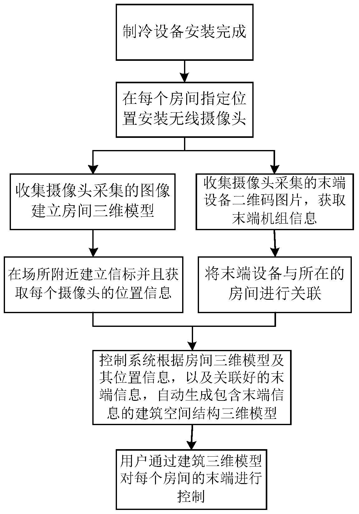
[0071] This embodiment provides an automatic generation system for a device control interface, including: an image acquisition device and an automatic generation device for the device control interface. The number of image acquisition devices is equal to the number of rooms in the venue, and they are installed at designated locations in each room to collect room images and equipment images of the room where they are located. The device for automatically generating the device control interface is the device described in the second embodiment above.

[0072] This embodiment uses the image acquisition device installed in the designated location of the room to automatically build a three-dimensional model of the room, automatically determine the location information of the room, and automatically determine the corresponding relationship between the equipment and the room, and then automatically based on the three-dimensional model of the room, the location information of the room and ...


PUM


Abstract

The invention discloses a method, a device and a system for automatically generating an equipment control interface. The method comprises the following steps: constructing a three-dimensional model ofeach room in a place according to automatically acquired room data; acquiring position information of each room; determining a corresponding relationship between each device in the place and each room according to the automatically acquired device data; and generating a place three-dimensional model as an equipment control interface according to the three-dimensional model of each room, the position information of each room and the corresponding relationship. The place three-dimensional model is automatically generated to serve as an equipment control interface, various data of a building donot need to be manually investigated on places. The development cost of an equipment control system is reduced, and the development period is shortened. Automatic association between the rooms and equipment is realized, and equipment managers do not need to remember names and positions of the equipment; an interface is friendly and easy to operate, equipment management personnel can better manageand control equipment in a building conveniently, and operation errors are reduced.

Description

Technical field [0001] The present invention relates to the technical field of equipment control, and in particular to a method, device and system for automatically generating equipment control interfaces. Background technique [0002] Now the control interface of large-scale refrigeration equipment is becoming more and more intelligent and user-friendly. For hotels, hospitals and other places, the host and terminal are controlled separately. After the manager turns on the host, the user can control the room temperature at the terminal by himself. [0003] For scenarios with fewer personnel, such as data centers, cold storage, etc., there may be only one general control system to control all terminals. Since this control system needs to control all the terminals, multiple terminals need to be displayed on the interface at the same time. It can be displayed in the form of a list, but this requires managers to remember the name and location of each end, otherwise wrong operations w...

Claims


Application Information

Patent Timeline
IPC IPC(8): G06F9/451G06T17/00
CPCG06T17/00G06F9/451
Inventor 卓明胜宋海川徐甘来颜超董小林
Owner GREE ELECTRIC APPLIANCES INC OF ZHUHAI
Features
  • Generate Ideas
  • Intellectual Property
  • Life Sciences
  • Materials
  • Tech Scout
  • Unparalleled Data Quality
  • Higher Quality Content
  • 60% Fewer Hallucinations
Learn More