
Image enhancement method and system

An image enhancement and image technology, applied in the field of image processing, can solve the problems of not enhanced detail information, overall dark restoration of image, and poor detail processing effect, so as to avoid the influence of highlight noise, reduce processing capacity, and improve processing efficiency effect

Active Publication Date: 2020-04-17
杭州鲁尔物联科技有限公司
View PDF2 Cites 2 Cited by
  • Summary
  • Abstract
  • Description
  • Claims
  • Application Information

AI Technical Summary

Problems solved by technology

The present invention effectively overcomes the problems that the existing dark channel prior method restores the overall dark image and poor visual effect, and the image defogging method of wavelet transform and atmospheric dissipation function does not enhance the detail information and the detail processing effect is poor. The defogged image can achieve detail enhancement at the same time, and the brightness change effect of the image is natural

Method used


Image

  • Image enhancement method and system
  • Image enhancement method and system
  • Image enhancement method and system

Examples


Embodiment 1

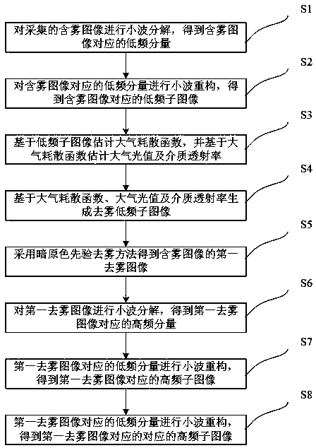
[0045] Such as figure 1 As shown, this embodiment proposes an image enhancement method, including:

[0046] S1. Perform wavelet decomposition on the collected foggy image to obtain low frequency components corresponding to the foggy image;

[0047] For images with fog, the fog mainly affects the low frequency part of the image. Therefore, the present invention first performs wavelet decomposition on the collected foggy image to obtain the low-frequency component corresponding to the foggy image, and then processes the low-frequency component of the foggy image to reduce the amount of data processing while ensuring the image defogging effect and improve Processing efficiency. The wavelet decomposition process of the foggy image is mainly to filter the horizontal and vertical directions of the image, and then sample the image to obtain the result of image decomposition. Wavelet basis functions include Haar (haar) wavelet, Daubechies (dbN) wavelet, Symlets (symN) wavelet, etc...

Embodiment 2

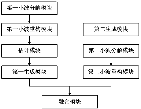
[0070] Such as figure 2 As shown, this embodiment proposes an image enhancement system, including:

[0071] The first wavelet decomposition module is used to perform wavelet decomposition on the collected foggy images to obtain low frequency components corresponding to the foggy images;

[0072] For images with fog, the fog mainly affects the low frequency part of the image. Therefore, the present invention first performs wavelet decomposition on the collected foggy image to obtain the low-frequency component corresponding to the foggy image, and then processes the low-frequency component of the foggy image to reduce the amount of data processing while ensuring the image defogging effect and improve Processing efficiency. The wavelet decomposition process of the foggy image is mainly to filter the horizontal and vertical directions of the image, and then sample the image to obtain the result of image decomposition. Wavelet basis functions include Haar (haar) wavelet, Daub...


PUM


Abstract

The invention discloses an image enhancement method and system, and the method comprises the steps: S1, carrying out wavelet decomposition of a collected foggy image, and obtaining a low-frequency component; S2, carrying out wavelet reconstruction on the low-frequency components, so that low-frequency sub-images can be obtained; S3, estimating an atmospheric dissipation function, an atmospheric light value and medium transmittance based on the low-frequency sub-images; S4, generating a defogging low-frequency sub-image based on the atmospheric dissipation function, the atmospheric light valueand the medium transmittance; S5, obtaining a first defogged image of the foggy image by adopting a dark channel prior defogging method; S6, performing wavelet decomposition on a first defogged imageto obtain a high-frequency component; S7, performing wavelet reconstruction on the high-frequency component to obtain a high-frequency sub-image corresponding to the first defogged image; and S8, performing wavelet fusion on the low-frequency sub-image and the high-frequency sub-image to generate a second defogged image. The second defogged image generated by the invention can realize detail enhancement at the same time, and the brightness change effect of images is natural.

Description

technical field [0001] The invention relates to the field of image processing, in particular to an image enhancement method and system. Background technique [0002] UAV aerial photography is widely used in many outdoor vision systems such as traffic monitoring and environmental monitoring. Due to the harsh weather environment in general mountainous areas, the possibility of foggy environment is high, the picture taken directly from the drone is not clear, and there is image noise. [0003] The invention patent application with the publication number CN 108460743 A discloses a dark channel-based UAV aerial image defogging algorithm, which obtains the dark channel image from the color foggy image, obtains the global atmospheric light component A from the dark channel image, and then Calculate the rough transmittance map according to the dark channel image, down-sample the coarse transmittance map, perform guided filtering and then up-sample to obtain the fine transmittance m...

Claims


Application Information

Patent Timeline
IPC IPC(8): G06T5/00
CPCG06T2207/20064G06T5/73
Inventor 包元锋张亮董梅胡辉宋杰
Owner 杭州鲁尔物联科技有限公司
Learn More