
BD B1 frequency band satellite navigation terminal antenna and working method thereof

A satellite navigation and terminal antenna technology, applied in the field of satellite navigation terminal antennas, can solve the problems of antenna size or shape limitation, loss, etc., and achieve the effects of increasing bandwidth, increasing axial ratio bandwidth, and expanding impedance and axial ratio bandwidth.

Active Publication Date: 2020-04-17
国网思极位置服务有限公司 +1
View PDF7 Cites 3 Cited by
  • Summary
  • Abstract
  • Description
  • Claims
  • Application Information

AI Technical Summary

Problems solved by technology

However, more energy needs to be lost to bring modes with similar radiation characteristics close to each other, and there are usually special constraints on the size or shape of the antenna

Method used


Image

  • BD B1 frequency band satellite navigation terminal antenna and working method thereof
  • BD B1 frequency band satellite navigation terminal antenna and working method thereof
  • BD B1 frequency band satellite navigation terminal antenna and working method thereof

Examples


Embodiment Construction

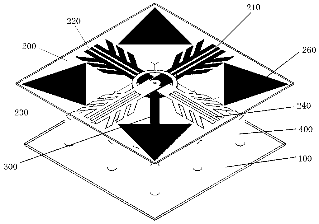
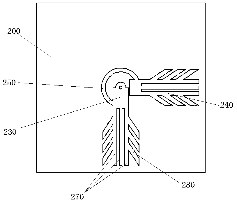
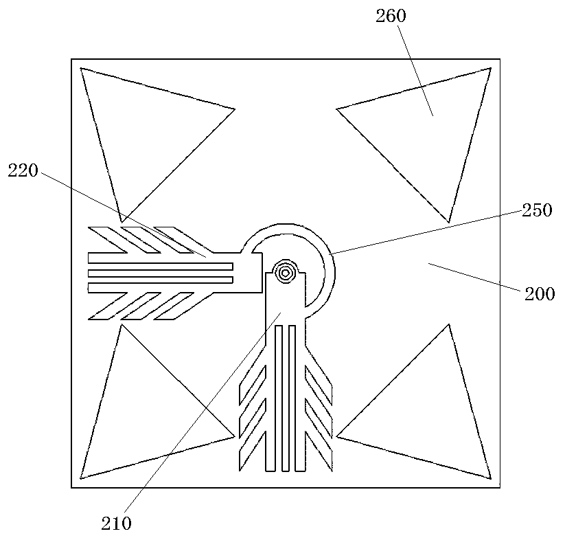
[0024] Such as Figure 1~4 As shown, a satellite navigation terminal antenna in the BD B1 frequency band includes a radiating plate 200 and a reflector 100 located below the radiating plate 200. The central parts of the radiating plate 200 and the reflecting plate 100 are connected with a coaxial line 300, and the radiation The upper side of the board 200 has an upper radiating arm group connected to the center of the coaxial line, the lower side of the radiating plate 200 has a lower radiating arm group staggered by 180° from the upper radiating arm group and connected to the outer center of the coaxial line, the upper and lower radiating arms The groups have a phase difference of 180°. The upper radiating arm group includes two upper radiating arms that are staggered by 90° and connected at one end through a conductor patch, that is, the first upper radiating arm 210 and the second upper radiating arm 220. The radiating arm group includes two lower radiating arms staggered b...


PUM


Abstract

The invention relates to a BD B1 frequency band satellite navigation terminal antenna and a working method thereof. The antenna comprises a radiation plate and a reflection plate, wherein the centralparts of the radiation plate and the reflection plate are connected with a coaxial line, an upper radiation arm group connected with the inner center of the coaxial line is arranged on the upper sidesurface of the radiation plate, the lower side surface of the radiation plate is provided with a lower radiation arm group staggered 180 DEG with the upper radiation arm group and connected with the outer center of the coaxial line, the upper radiation arm group comprises two upper radiation arms staggered 90 DEG and connected with each other through one inward ends, the lower radiation arm groupcomprises two lower radiation arms staggered 90 DEG and connected with each other through one inward ends, four vertical metal columns distributed in a rectangular shape are further connected betweenthe radiation plate and the reflection plate, and radiation patches corresponding to the vertical metal columns in position in an up-down one-to-one mode are arranged on the lower side surface of theradiation plate. According to the antenna, a coaxial line feeding method is adopted, the upper layer is connected with the inner center of the coaxial line, the lower layer is connected with the outercenter of the coaxial line, a 90-DEG phase difference is generated, the circularly polarized radiation is achieved, the coupling effect is achieved through the short-circuit patch and the radiation arm, and the bandwidth of the antenna can be increased.

Description

technical field [0001] The invention relates to a BD B1 frequency band satellite navigation terminal antenna and a working method thereof, belonging to the technical field of wireless communication. Background technique [0002] Circularly polarized (CP) antennas are highly favored by certain wireless communication systems, such as global positioning systems, satellite communication / navigation systems, and radio frequency identification systems, due to their ability to mitigate polarization mismatch and suppress multipath interference. Designing two electric field components with equal amplitude and quadrature phase is a common technique to implement CP antennas. CP antennas can be divided into single-fed and double-fed according to the feeding method. Generally, single-fed antennas have simpler feed networks but narrower axial ratio (AR) bandwidth, while double-fed antennas can provide wider AR bandwidth but require external hybrid couplers or power dividers, which Will in...

Claims


Application Information

Patent Timeline
Patent Type & Authority Applications(China)
IPC IPC(8): H01Q1/36H01Q1/38H01Q1/50H01Q5/10H01Q5/307H01Q15/24H01Q19/10
CPCH01Q1/36H01Q1/38H01Q1/50H01Q15/24H01Q5/10H01Q5/307H01Q19/104
Inventor 臧志斌吉福龙庞辉聂海涛廖宝全
Owner 国网思极位置服务有限公司
Learn More