DC bias calibration device and method of zero intermediate frequency waveform generation system

A waveform generation and DC bias technology, applied in the field of signal processing, can solve problems such as increasing costs, and achieve the effect of improving economy

Pending Publication Date: 2020-04-17
INSPUR ARTIFICIAL INTELLIGENCE RES INST CO LTD SHANDONG CHINA
View PDF7 Cites 2 Cited by
  • Summary
  • Abstract
  • Description
  • Claims
  • Application Information

AI Technical Summary

Problems solved by technology

In order to measure the output waveform amplitude as accurately as possible in the traditional method of suppressing

Method used


Image

  • DC bias calibration device and method of zero intermediate frequency waveform generation system
  • DC bias calibration device and method of zero intermediate frequency waveform generation system
  • DC bias calibration device and method of zero intermediate frequency waveform generation system

Examples


Embodiment 1

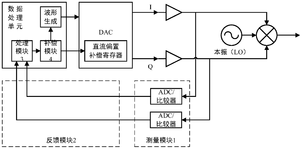
[0049] combined with figure 1 , the present embodiment proposes a DC offset calibration device for a zero-IF waveform generation system, which includes a measurement module 1, a feedback module 2, a processing module 3 and a compensation module 4, which respectively measure, feed back, and Processing and Compensation.

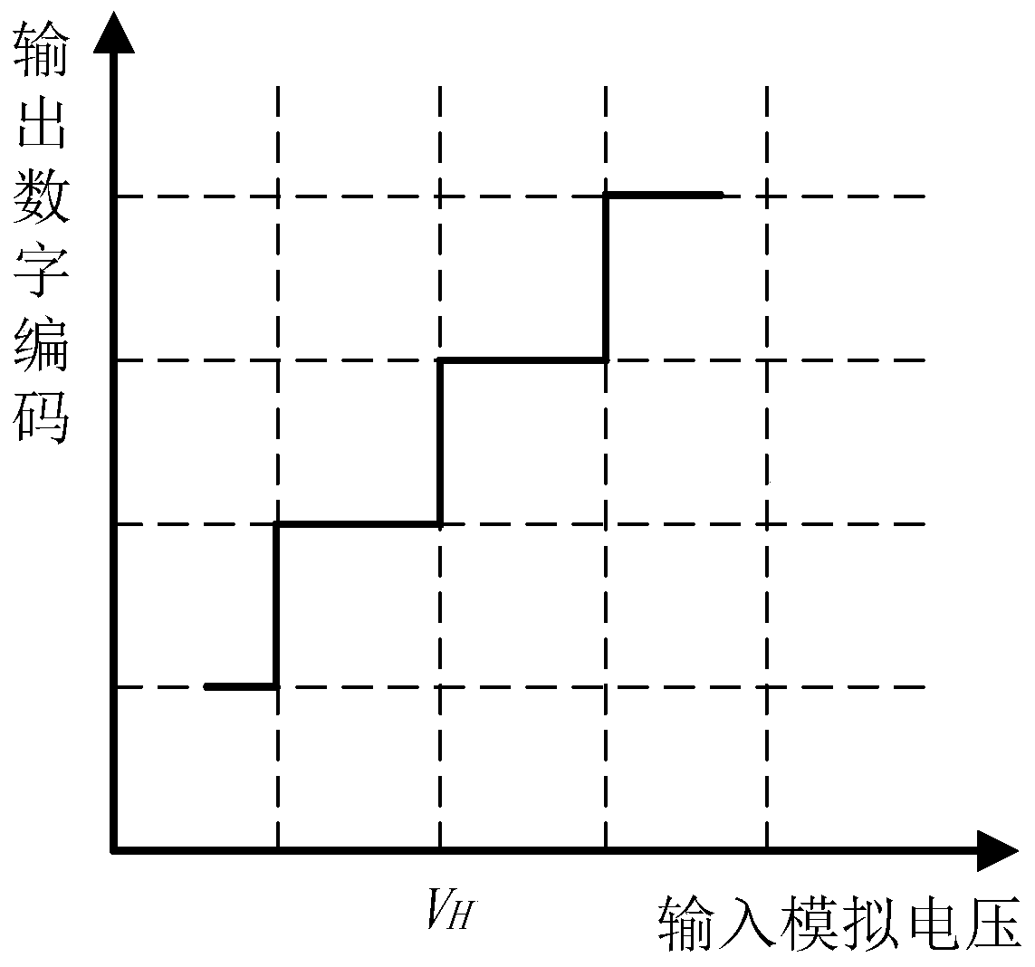
[0050] The measurement module 1 involved is used to measure the voltage amplitude of the output waveform signal of the zero-IF waveform generation system, and quantize the measurement result into digital data, whose quantization digits are much smaller than the digits of the DAC on the output channel of the zero-IF waveform generation system. During specific implementation, the number of quantization bits of the measurement module 1 may be a 1-bit AD converter or a 1-bit comparator.

[0051] The feedback module 2 is connected to the measurement module 1 and used to feed back the measurement results to the data processing unit of the zero-IF waveform generation...

Embodiment 2

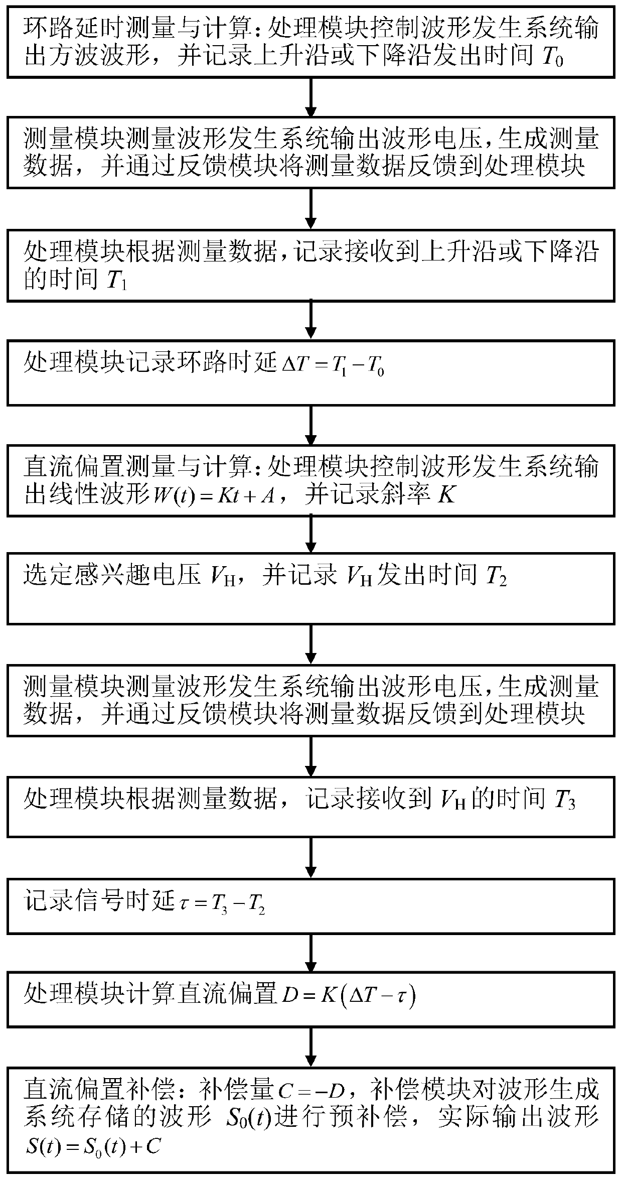
[0056] Based on the DC offset calibration device of Embodiment 1, combined with the attached figure 2 , this embodiment provides a DC offset calibration method for a zero-IF waveform generation system, and its implementation process includes:

[0057] 1) Loop delay measurement and calculation:

[0058] 1.1) The processing module 3 controls the waveform generation system to output a square wave waveform, and records the rising or falling edge sending time T 0 ;

[0059] 1.2) The measurement module 1 measures the output waveform voltage of the waveform generation system, generates measurement data, and feeds back the measurement data to the processing module 3 through the feedback module 2;

[0060] 1.3) The processing module 3 records the time T of receiving the rising edge or the falling edge according to the measurement data 1 ;

[0061] 1.4) Processing module 3 records loop time delay ΔT=T 1 -T 0 .

[0062] 2) DC bias measurement and calculation:

[0063] 2.1) The p...


PUM


Abstract

The invention discloses a DC bias calibration apparatus and method of a zero-intermediate-frequency waveform generation system, and relates to the technical field of signal processing. The device comprises a measurement module, a feedback module, a processing module and a compensation module. The measurement module is used for measuring waveform signals output by a zero intermediate frequency waveform generation system; the feedback module is connected with the measurement module and used for feeding back a measurement result to a data processing unit of the zero intermediate frequency waveform generation system; the processing module is connected with the feedback module, is deployed in a data processing unit of the zero intermediate frequency waveform generation system and is used for processing the measurement data so as to obtain a DC bias compensation amount; and the compensation module is connected with the feedback module, is deployed in a data processing unit of the zero intermediate frequency waveform generation system, and is used for calibrating an output waveform signal according to the DC bias compensation amount. According to the invention, the measurement of the amplitude is converted into the measurement of the time delay, and then the calibration of the DC bias is completed.

Description

technical field [0001] The invention relates to the technical field of signal processing, in particular to a DC offset calibration device and method for a zero-IF waveform generation system. Background technique [0002] In modern digital signal systems, zero-IF structure is widely used in waveform generating devices. Zero-IF structure waveform generating devices include data processing unit, memory, DAC and analog signal path. The main control part of the data processing unit is used to control the generation, storage and reading of digital waveform data. The memory is used to store digital waveform data under the control of the main control part. The DAC is used to convert the digital waveform data into I and Q two-way quadrature analog signals and output them to the mixer under the control of the main control part, and mix with the microwave signal from the microwave source at the mixer to convert the The frequency of the measurement and control waveform is moved to the...

Claims


Application Information

Patent Timeline
IPC IPC(8): H03M1/10G01R29/02G01R29/04
CPCH03M1/1009G01R29/02G01R29/04
Inventor 赵寰金长新刘强
Owner INSPUR ARTIFICIAL INTELLIGENCE RES INST CO LTD SHANDONG CHINA
Why Eureka
Try Eureka