
Cylinder pushing hoisting device

A lifting device and cylinder technology, applied in the direction of lifting device, lifting frame, transportation and packaging, etc., can solve the problems of single structure of the lifting device, inability to replace the claws, and insufficient internal structural strength of the device, etc., to achieve improved Load capacity, easy disassembly effect

Inactive Publication Date: 2020-04-21
TIANCHANG TIANXIANG GRP
View PDF0 Cites 1 Cited by
  • Summary
  • Abstract
  • Description
  • Claims
  • Application Information

AI Technical Summary

Problems solved by technology

[0004] The purpose of the present invention is to provide a cylinder-propelled lifting device to solve the problem that the cylinder-propelled lifting device proposed in the above-mentioned background technology has a single structure, which cannot meet the current work requirements, the internal structure of the device is not strong enough, and the jaw type is single and cannot be carried out. Replacement of other types of jaws, lack of item lifting and matching mechanism, etc.

Method used


Image

  • Cylinder pushing hoisting device
  • Cylinder pushing hoisting device
  • Cylinder pushing hoisting device

Examples


Embodiment Construction

[0026] The following will clearly and completely describe the technical solutions in the embodiments of the present invention with reference to the accompanying drawings in the embodiments of the present invention. Obviously, the described embodiments are only some, not all, embodiments of the present invention.

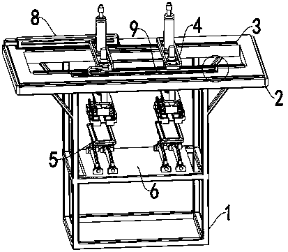
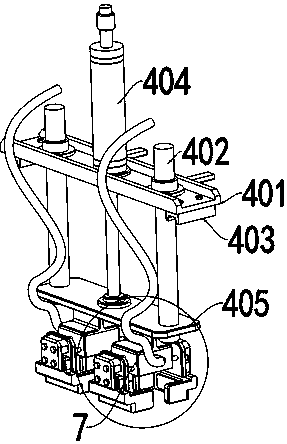
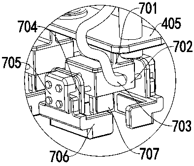
[0027] see Figure 1 to Figure 6 , a kind of embodiment that the present invention provides: a kind of air cylinder pushes lifting device, comprises device frame 1, and the inner side of device frame 1 is provided with placement plate 6, and the upper end surface of device frame 1 is installed with top end fixed plate 2, and top end fixed plate The inner side of 2 is provided with a square groove, the upper end surface of the top fixed plate 2 is symmetrically installed with two slide rails 3, and the upper end surface of slide rail 3 is installed with two cylinder lifting mechanisms 4, through the effect of cylinder lifting mechanism 4, can realize The lifting and e...


PUM


Abstract

The invention discloses a cylinder pushing hoisting device, relates to the technical field of cylinder pushing hoisting, and solves the problems that a cylinder pushing hoisting structure is simplex and lacks auxiliary lifting. The cylinder pushing hoisting device comprises a device frame, wherein a placing plate is arranged on the inner side of the device frame, a top end fixing plate is arrangedon the upper end face of the device frame, a square groove is formed in the inner side of the top end fixing plate, two sliding rails are symmetrically arranged on the upper end face of the top end fixing plate, two cylinder lifting mechanisms are arranged on the upper end faces of the sliding rails, a power source placing frame is arranged on one side of the cylinder lifting mechanisms, an electric cylinder is mounted on the other side of the cylinder lifting mechanisms, two object frames are mounted on the upper end face of the placing plate, and starting grabbing mechanisms are mounted onthe lower end faces of the cylinder lifting mechanisms. A cylinder lifting auxiliary mechanism and a claw replacing function are added to the cylinder pushing hoisting device.

Description

technical field [0001] The invention relates to the technical field of cylinder-propelled lifting, in particular to a cylinder-propelled lifting device. Background technique [0002] With the rapid development of social economy, some equipment currently used in the manufacture and production of oil tank truck heads, in the prior art, most of them use motor screw to realize the lifting of the power head. This method makes the machine head The lifting is not flexible, the adjustment of the effective size of the processed parts is difficult to control, and there is no elasticity, which makes the moving parts wear fast and the failure rate is high. [0003] However, the existing cylinder-propelled lifting device has a single structure and cannot meet the current work requirements. The internal structure of the device is not strong enough, and the claw type is single and cannot be replaced with other types of claws, and lacks an item lifting and matching mechanism; therefore, it ...

Claims


Application Information

Patent Timeline
Patent Type & Authority Applications(China)
IPC IPC(8): B65G47/90B66F7/06B66F7/28
CPCB65G47/901B66F7/0608B66F7/065B66F7/28
Inventor 张厚明
Owner TIANCHANG TIANXIANG GRP
Learn More