Anti-jumping conductive jig

An anti-jumping and jig technology, applied in the electrolysis process, electrolysis components, etc., can solve the problems that the surface of the strip material cannot be uniformly deposited, the contact is poor, and the working position is easy to deviate, and the effect of avoiding poor contact is achieved.

Pending Publication Date: 2020-04-21
KUNSHAN SOKAY AUTOMATION TECH CO LTD
View PDF0 Cites 4 Cited by
  • Summary
  • Abstract
  • Description
  • Claims
  • Application Information

AI Technical Summary

Problems solved by technology

[0003] For shells, terminals, and plates, the above-mentioned parts are produced as strip materials during electroplating for continuous production, and strip materials are usually transported by traction in order to facilitate continuous electroplating during electroplating. The actual production The electroplating terminals are all long (the length of the electroplating machine is more than 50 meters). When the strip-shaped material is electroplated, it will cause the strip-shaped material to be difficult to fix, the working position is easy to deviate and the contact is poor, resulting in uneven surface of the strip-shaped material Deposition or no deposition at all, reducing work efficiency, there are improvements in the existing technology

Method used


Image

  • Anti-jumping conductive jig
  • Anti-jumping conductive jig
  • Anti-jumping conductive jig

Examples


Embodiment Construction

[0033] The present invention will be described in further detail below in conjunction with the accompanying drawings.

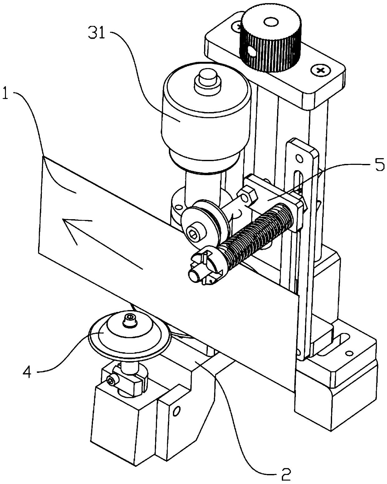
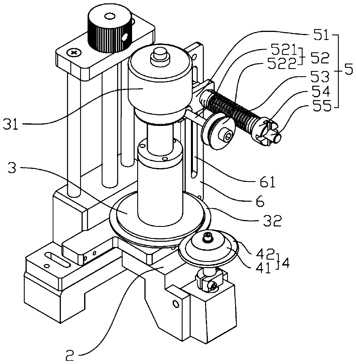
[0034] Such as figure 1 and figure 2 As shown, a conductive fixture for anti-jumping includes a fixed base plate and a conductive wheel rotatably arranged on the fixed base plate. The side of the conductive wheel away from the fixed base plate is provided with a mercury connector connected to an external power grid. The fixed base plate also has a It includes a guide wheel set parallel to the conductive wheel and an anti-jumping component for pressing the strip-shaped material. A gap for the strip-shaped material to pass is formed between the guide wheel and the conductive wheel. The anti-jumping component is opposite to the guide wheel Set on both sides of the strip-shaped material, the anti-jumping material assembly includes a rotating shaft and an adjusting plate that is rotated on the rotating shaft. The side of the adjusting plate away from the rotatin...


PUM


Abstract

The invention discloses an anti-jumping conductive jig comprising a fixed bottom plate and a conductive wheel. The fixed bottom plate further comprises a guide wheel parallel to the conductive wheel and an anti-jumping assembly for pressing the strip-shaped material. A gap for a strip-shaped material to penetrate through is formed between the guide wheel and the conductive wheel, the anti-jumpingassembly and the guide wheel are oppositely arranged on the two sides of the strip-shaped material, the anti-jumping assembly comprises a rotating shaft and an adjusting plate rotationally arranged onthe rotating shaft, a material pressing block is arranged on the side, away from the rotating shaft, of the adjusting plate, and an elastic piece is arranged on the other side. The anti-jumping assembly enables the strip-shaped material to have a movement trend towards one side of the guide wheel, the strip-shaped material can be positioned in the gap between the guide wheel and the conductive wheel, the strip-shaped material is prevented from jumping in the axis direction of the conductive wheel, the strip-shaped material and the conductive guide wheel are fully kept in contact through the guide wheel and the anti-jumping assembly, deviation and poor contact of the transverse working position of the strip-shaped material can be avoided and thus the surface of the strip-shaped material isensured to be evenly deposited.

Description

technical field [0001] The invention relates to the technical field of electroplating, in particular to a conductive jig for preventing material jumping. Background technique [0002] Electroplating is the process of plating a thin layer of other metals or alloys on some metal surfaces by using the principle of electrolysis. In most electronic connectors, the terminals have to be surface-treated, and electroplating is generally used. There are two main reasons for this: 1. To protect the base material of the terminal reed from corrosion; 2. To optimize the performance of the terminal surface and establish And maintain the contact interface between the terminals, especially the film layer control. [0003] For shells, terminals, and plates, the above-mentioned parts are produced as strip materials during electroplating for continuous production, and strip materials are usually transported by traction in order to facilitate continuous electroplating during electroplating. The...

Claims


Application Information

Patent Timeline
Patent Type & Authority Applications(China)
IPC IPC(8): C25D7/06C25D17/00
CPCC25D7/0657
Inventor 张文标
Owner KUNSHAN SOKAY AUTOMATION TECH CO LTD
Why Eureka
Try Eureka