Supercharge Your Innovation With Domain-Expert AI Agents!

Device and method for treating kitchen waste

A technology for processing equipment and kitchen waste, applied in water supply equipment, indoor sanitary piping equipment, buildings, etc., can solve the problems of unfavorable screening efficiency, large crushing load, and no selectivity in crushing, and achieves improved screening effect and high cutting efficiency. Effect

Active Publication Date: 2021-02-19
南京科泷节能科技有限公司
View PDF1 Cites 0 Cited by
  • Summary
  • Abstract
  • Description
  • Claims
  • Application Information

AI Technical Summary

Problems solved by technology

[0003] However, the above-mentioned device needs to crush all the particles when it is used. The crushing is not selective, and the crushing load is relatively large, which is not conducive to improving the screening efficiency and also increases the processing burden.

Method used


Image

  • Device and method for treating kitchen waste
  • Device and method for treating kitchen waste
  • Device and method for treating kitchen waste

Examples


Embodiment 1

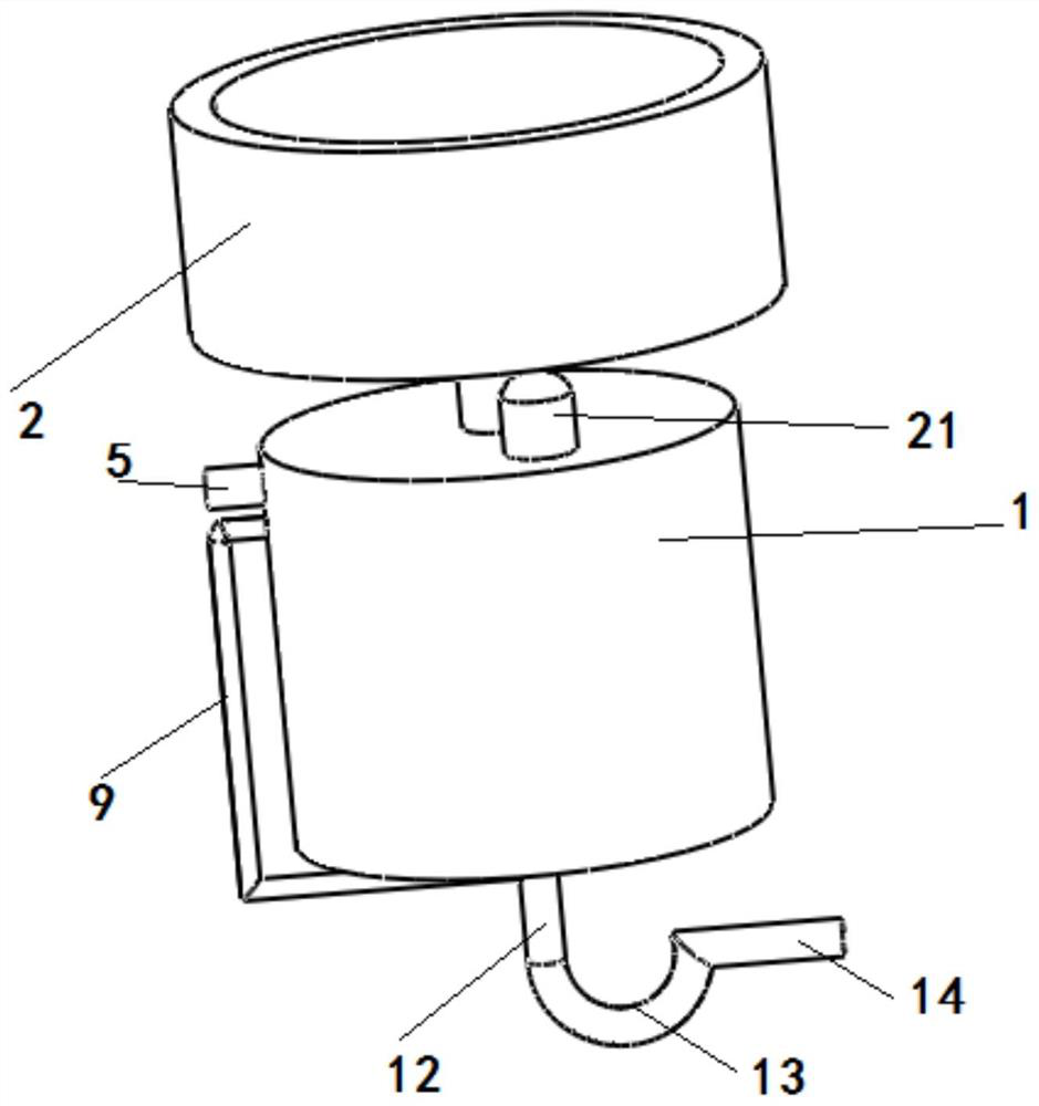
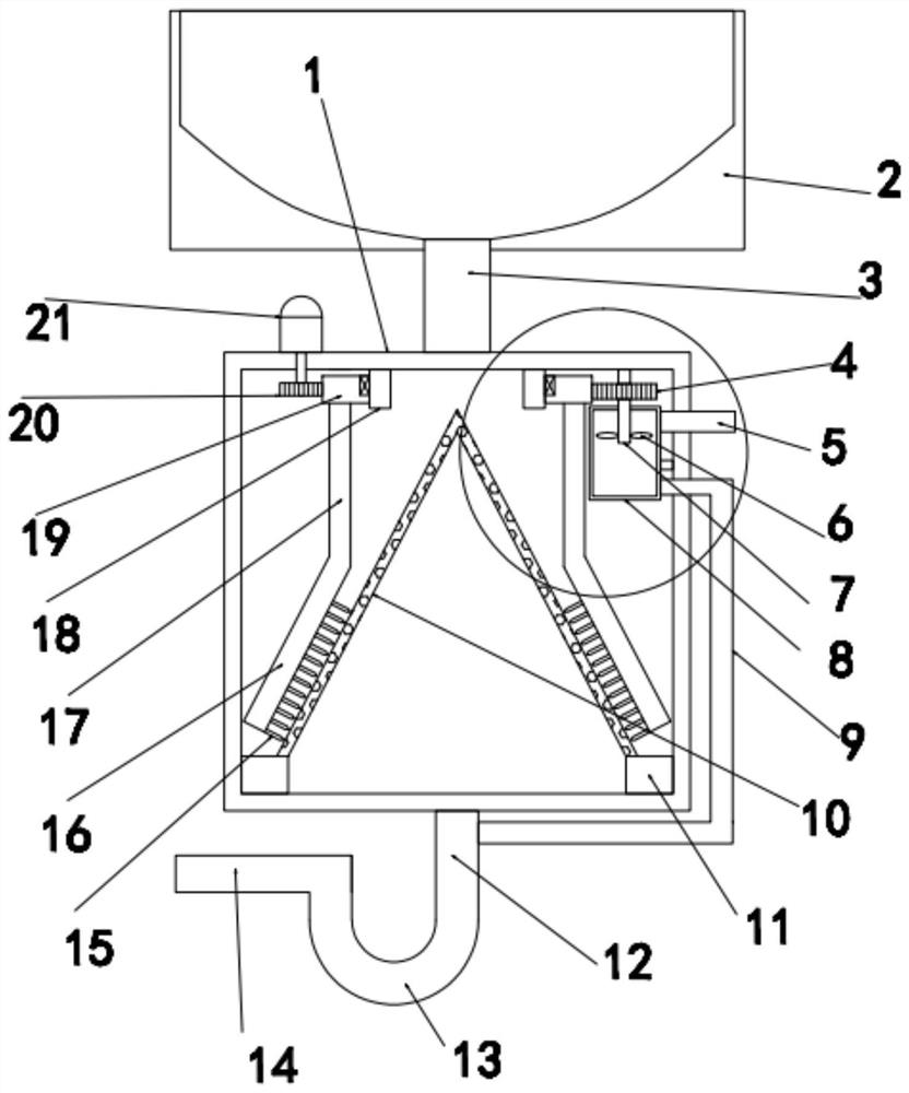
[0025] see Figure 1-3 , in an embodiment of the present invention, a kitchen waste treatment device includes a water receiving pool 2 for cleaning kitchen utensils, the discharge end of the lower end of the water receiving pool 2 communicates with the upper end of the treatment box 1 at the upper end of the treatment box 1 through a communication pipe 3, and the The drain end of the lower end of the treatment box 1 is provided with a drainpipe 12, the lower end of the drainpipe 12 is connected to a U-shaped pipe 13 for buffering clean water to realize a water seal, and the other end of the U-shaped pipe 13 is connected to a sewage conduit 14. There is a cutting part for sorting and cutting the materials, and the inside of the processing box 1 is provided with a filter screen 10 for filtering the materials. The filter screen 10 is a conical filter structure, and the filter screen 10 is coaxially arranged with the connecting pipe 3 , the lower end of the filter screen 10 is pro...

Embodiment 2

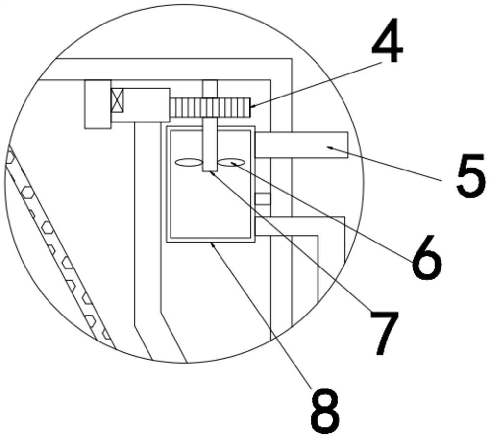
[0033] The difference from Embodiment 1 is that the inner wall of the air extraction box 8 is provided with an ultraviolet disinfection lamp for disinfection and sterilization, and a waterproof cover is provided outside the ultraviolet disinfection lamp.

[0034] The working principle of the present invention is: when the material falls along the connecting pipe 3, the material will slide down along the top of the conical filter screen, the qualified material will pass through the filter screen 10 during the sliding process, and the unqualified material will pass through the filter screen 10 along the cone-shaped filter screen. Shape filter screen 10 slides to the bottom, and under the effect of drive motor 21, drive gear 20 drives suspender 17 to rotate through driven gear 19, and suspender 17 drives cutting knife 15 to rotate, thereby the material that cannot pass through filter screen 10 is cut Cut until the material passes through the filter screen 10, avoiding the problem ...


PUM


Abstract

The invention discloses a kitchen garbage disposal device and method, comprising a water receiving pool for cleaning kitchen utensils, a discharge end at the lower end of the water receiving pool is communicated with the upper end of the treatment box at the upper end of the treatment box through a communication pipe, and the drainage end at the lower end of the treatment box is connected to the upper end of the treatment box. There is a drain pipe, a cutting part for sorting and cutting materials is arranged inside the processing box, a filter screen for filtering materials is arranged inside the processing box, the filter screen is a conical filter structure, and the lower end of the filter screen is There is a piston block slidingly matched with the inside of the treatment box. This movable setting can facilitate the replacement of the filter screen. The present invention is designed in view of the disadvantages of the existing device, and does not cut the qualified material, and realizes Sorting and cutting, high cutting efficiency, can generate negative pressure at the bottom of the processing box, so that the material on the filter screen can quickly pass through the mesh holes, thereby improving the screening effect.

Description

technical field [0001] The invention relates to the technical field of kitchen equipment, in particular to a kitchen waste treatment device and method. Background technique [0002] With the development of cities and the continuous improvement of people's living standards, in people's lives, a lot of food waste will be produced every day and every meal, such as the leftovers after people choose vegetables, wash vegetables, and wash dishes. The water pipe is easy to cause the sewer pipe to be blocked. If the leftovers of vegetables are fished out from the water tank by hand, the cleaning process is quite troublesome. The crushing teeth and filter plate are installed in the crushing box, and the kitchen waste is better crushed and then discharged, preventing the waste from blocking the water pipe, and it is no longer necessary to remove the leftovers from the sink by hand, reducing trouble, and through the floating The ball cooperates with the funnel-shaped anti-odor groove, ...

Claims


Application Information

Patent Timeline
Patent Type & Authority Patents(China)
IPC IPC(8): E03C1/264E03C1/266
CPCE03C1/264E03C1/2665
Inventor 程金富
Owner 南京科泷节能科技有限公司
Features
  • R&D
  • Intellectual Property
  • Life Sciences
  • Materials
  • Tech Scout
  • Unparalleled Data Quality
  • Higher Quality Content
  • 60% Fewer Hallucinations
Learn More