Assembly type buckling restrained brace capable of visually inspecting segmented restraint

A buckling restraint, prefabricated technology, applied in protective buildings/shelters, building components, earthquake-proof, etc., can solve the problems of damage observation and waste of supports that cannot be buckling restraint, so as to reduce construction workload and avoid material waste. , the effect of easy installation

Pending Publication Date: 2020-04-21
NORTHEAST FORESTRY UNIVERSITY
View PDF7 Cites 1 Cited by
  • Summary
  • Abstract
  • Description
  • Claims
  • Application Information

AI Technical Summary

Problems solved by technology

However, in post-earthquake repairs, it is necessary to disassemble all the peripheral restraint devices of the fabricated buckling-restrained brace before visually inspecting the buckling-restrained brace, and it is impossible to quickly observe the damage of the buckling-restrained brace
[0004] In addition, even if local damage to the peripheral restraint device is found after the earthquake, the entire peripheral restraint device needs to be replaced, resulting in serious waste

Method used


Image

  • Assembly type buckling restrained brace capable of visually inspecting segmented restraint
  • Assembly type buckling restrained brace capable of visually inspecting segmented restraint
  • Assembly type buckling restrained brace capable of visually inspecting segmented restraint

Examples


Embodiment 1

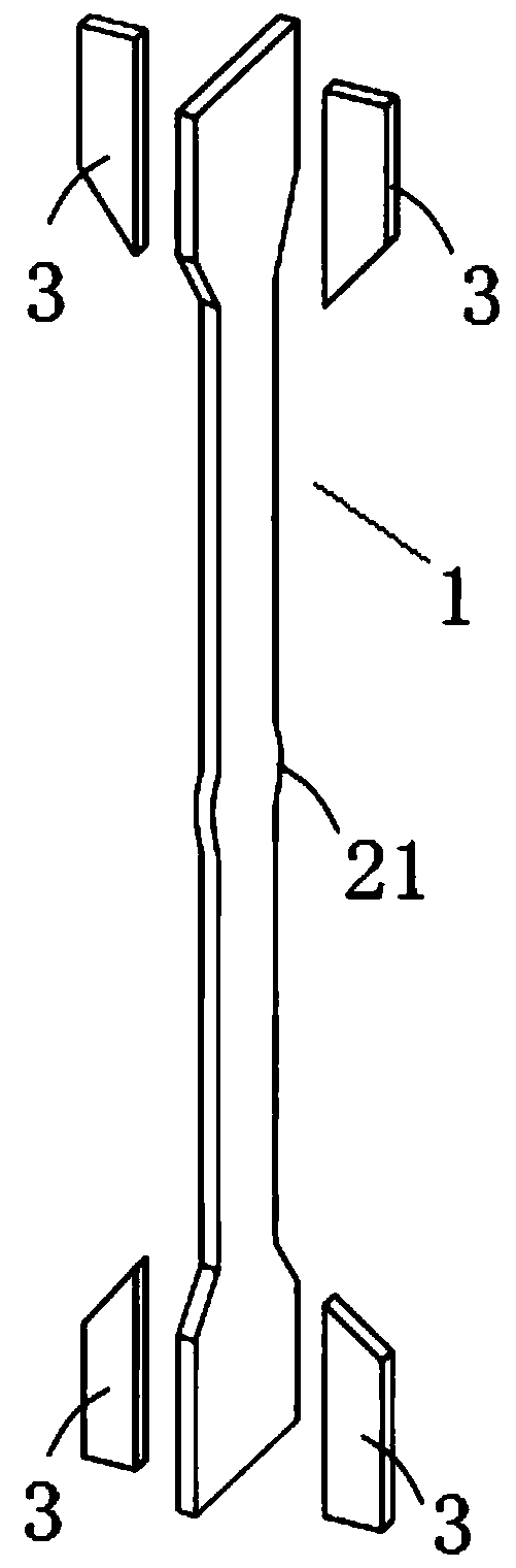
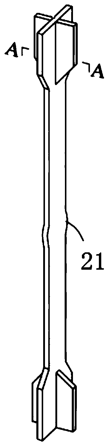
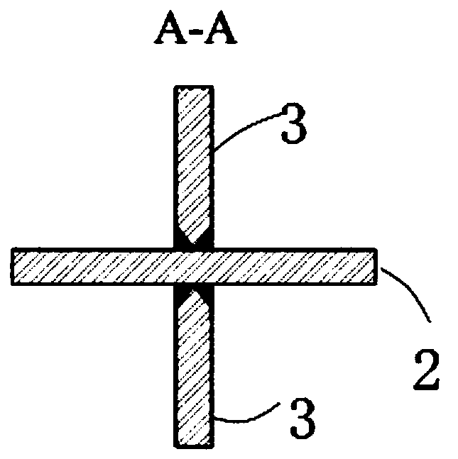
[0052] A fabricated buckling-restrained brace with visual inspection of segmental constraints, such as Figure 1-3 As shown, it includes a supporting inner core 1. The supporting inner core 1 includes an inline core plate 2 and a first reinforcing rib 3. The edges on both sides of the middle part of the inline core plate 2 have limit protrusions 21. The first reinforcing ribs Two ribs 3 are fixedly connected to both ends of the inline core plate 2, and symmetrically distributed on the two surfaces of the ends of the inline core plate 2, and welded perpendicularly thereto;

[0053] Such as Figure 4-5 As shown, along the length direction of the supporting inner core 1, there are sequentially detachably connected a first end peripheral restraint device 5, a middle peripheral restraint device 6 and a second end peripheral restraint device 4; the first end peripheral restraint device 5 is set as Two groups, relatively distributed on the two surfaces of one end of the supporting i...

Embodiment 2

[0062] Different from Embodiment 1, the supporting inner core 1 is composed of a cross-shaped core plate 22 and a second reinforcing rib 31. The edges on both sides of the middle part of the cross-shaped core plate 22 have limit protrusions 21, and the ends of the cross-shaped core plate 22 The fillet welds on both sides of the second rib plate 31 are connected between two adjacent core plates at the top; correspondingly, the end constraining plate 9 and the middle constraining plate 14 are all symmetrical structures, and the end constraining plate 9 has a wide cross-section The two middle parts are provided with a notch for accommodating the second reinforcing rib 31 along the vertical direction, and the middle part of the narrow section is also provided with a through groove adapted to the cross-shaped core plate 22; The through groove for the cross-shaped core plate 22; the side where the end connecting plate 11 is close to the cross-shaped core plate 22 is also provided wit...


PUM


Abstract

The invention discloses an assembly type buckling restrained brace capable of visually inspecting segmented restraint. The assembly type buckling restrained brace capable of visually inspecting the segmented restraint comprises a supporting inner core, cushion blocks and limiting cushion blocks, wherein first end peripheral restraint devices, middle peripheral restraint devices and second end peripheral restraint devices are detachably connected in the length direction of the supporting inner core, and the first end peripheral restraint devices, the middle peripheral restraint devices and thesecond end peripheral restraint devices are relatively distributed on two surfaces of the supporting inner core and are detachably connected with the supporting inner core; the cushion blocks are arranged between the two groups of first end peripheral restraint devices and the two groups of second end peripheral restraint devices in a filling mode and are detachably connected with the first end peripheral restraint devices and the second end peripheral restraint devices; and the limiting cushion blocks are arranged between the two groups of middle peripheral restraint devices in a filling modeand are detachably connected with the middle peripheral restraint devices. According to the assembly type buckling restrained brace capable of visually inspecting the segmented restraint, the damagedparts can be replaced in segments to avoid waste of materials; and only the positions of the cushion blocks and the limiting cushion blocks on the two side surfaces of the supporting inner core are blocked, and the rest of the positions are completely visible, and convenience is provided for monitoring the deformation and damage of the supporting inner core of the buckling restrained brace.

Description

technical field [0001] The invention relates to the technical field of shock absorption of civil engineering structures, and more specifically relates to an assembled buckling-constrained support with visually inspectable segmental constraints. Background technique [0002] Buckling-restrained bracing is composed of bracing inner core and peripheral restraining device. The bracing inner core mainly bears the axial force and uses its plastic deformation to consume seismic energy. Lateral buckling, there is a certain gap between the inner core and the peripheral restraint device to ensure that the supporting inner core will not be blocked due to lateral expansion when it is compressed. [0003] At present, the peripheral restraint devices of prefabricated buckling-restrained braces can be divided into three categories according to the materials and combinations of the restraint devices: concrete prefabricated peripheral restraint units, steel pipe concrete composite prefabrica...

Claims


Application Information

Patent Timeline
Patent Type & Authority Applications(China)
IPC IPC(8): E04B1/98E04H9/02
CPCE04B1/98E04H9/021
Inventor 鲁军凯程东辉
Owner NORTHEAST FORESTRY UNIVERSITY
Why Eureka
Try Eureka