
Assembly type laminated slab anchoring structure convenient to construct and connecting mode thereof

An anchoring structure and laminated board technology, applied in the direction of structural elements, floor slabs, building components, etc., can solve the problems of large workload and low construction efficiency, and achieve the effect of reducing the use of materials, convenient construction, and reducing workload.

Pending Publication Date: 2020-04-21
UNIV OF JINAN
View PDF5 Cites 1 Cited by
  • Summary
  • Abstract
  • Description
  • Claims
  • Application Information

AI Technical Summary

Problems solved by technology

[0005] Since the laminated floor slab is an assembled prefabricated slab, it still needs to be supported by a frame during construction; in the prior art, a relative anchorage system is usually used for fixed support, but it also requires on-site reinforcement binding, which leads to a large amount of work and heavy construction costs. The problem of inefficiency

Method used


Image

  • Assembly type laminated slab anchoring structure convenient to construct and connecting mode thereof
  • Assembly type laminated slab anchoring structure convenient to construct and connecting mode thereof
  • Assembly type laminated slab anchoring structure convenient to construct and connecting mode thereof

Examples


Embodiment 1

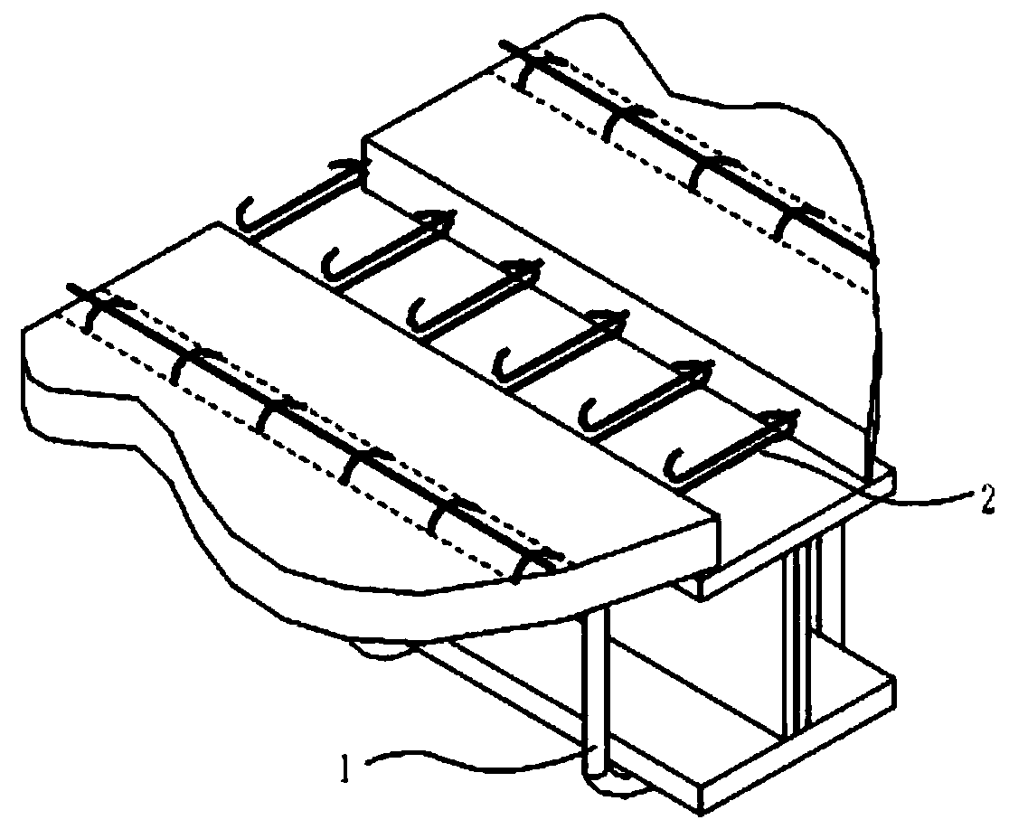
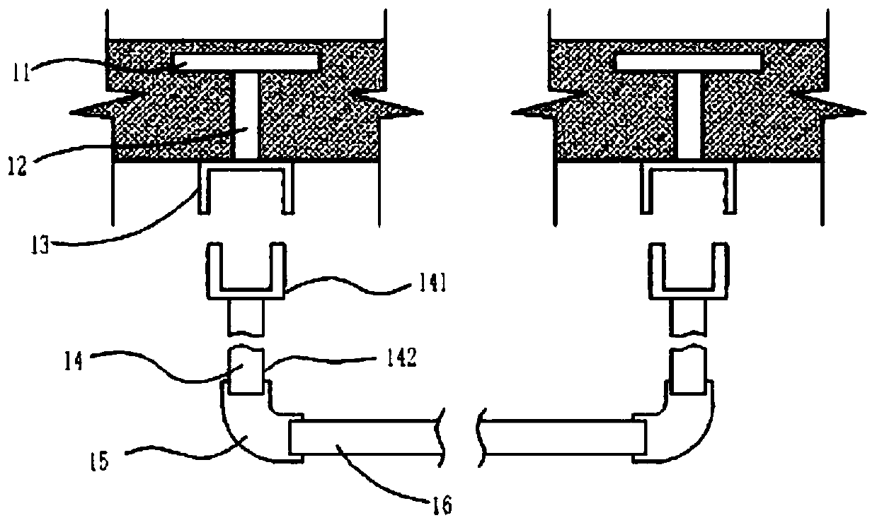
[0033] Embodiment 1: as figure 1 , 2 A prefabricated laminated plate anchoring structure that is convenient for construction is shown, including a first anchor 1 for anchoring connection with the outside, and a second anchor 2 for anchoring connection between the prefabricated laminated plates themselves;

[0034] The first anchor 1 includes embedded parts and connectors;

[0035] The embedded part includes the embedded bottom plate 11, the embedded connecting rod 12, and the first connecting cap 13; the connecting part includes the connecting rod 14, the connecting elbow 15 and the second connecting rod 16, and the connecting rod 14 includes the second connecting cap 141 and the a connecting rod 142;

[0036] One end of the pre-embedded connecting rod 12 is welded on the pre-embedded bottom plate 11, and the first connecting cap 13 is installed on the other end of the pre-embedded connecting rod 12;

[0037] like figure 2 As shown, the second connecting cap 141 can be in...

Embodiment 2

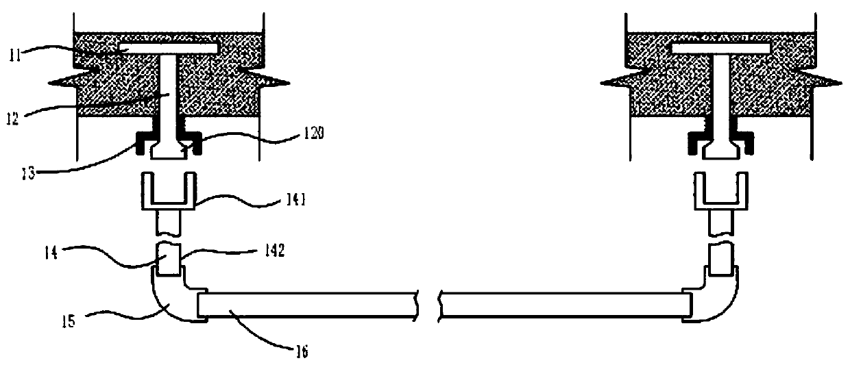
[0045] Embodiment 2: Different from Embodiment 1: as image 3As shown, the end of the embedded connecting rod 12 connected to the first connecting cap 13 is equipped with a mounting head 120, and the outer wall of the mounting head 120 is provided with threads; the first connecting cap 13 is movably installed on the embedded connecting rod 12, and the first connecting The inner wall of the cap 13 is provided with threads, and the inner and outer walls of the second connecting cap 141 are provided with threads corresponding to the threads on the mounting head 120 and the first connecting cap 13; The outer wall of the second connecting cap 141 is threadedly connected with the first connecting cap 13 .

Embodiment 3

[0046] Embodiment 3: Different from Embodiment 2: as Figure 4 As shown, the embedded base plate 11 adopts a channel steel base plate.


PUM


Abstract

The invention discloses an assembly type laminated slab anchoring structure convenient to construct and a connecting mode thereof. The anchoring structure comprises a first anchoring part used for being in anchoring connection with the outside and a second anchoring part used for being in anchoring connection between assembly type laminated slabs. The connecting mode comprises the steps that afterthe first anchoring part is prefabricated, then when the assembly type laminated slabs are prepared, the first anchoring part and the second anchoring part are locally pre-buried in concrete of the prefabricated layer, and finally in later laminated slab assembly construction, the first anchoring part and the second anchoring part are completely assembled, and then concrete preparation of a cast-in-place layer is carried out. According to the assembly type laminated slab anchoring structure convenient to construct and the connecting mode thereof, the adopted first anchoring part can effectively ensure fixation of the assembly type laminated slabs when the assembly type laminated slabs are mounted; and the adopted anchoring structure has better stability, binding of field steel bars can beeffectively reduced in actual field construction, and construction is more convenient.

Description

technical field [0001] The invention relates to the technical field of prefabricated laminated panels, in particular to an anchoring structure of prefabricated laminated panels which is convenient for construction and a connection method thereof. Background technique [0002] The prefabricated building refers to the transfer of a large number of on-site operations in the traditional construction method to the factory, where the building components and accessories are processed and manufactured, transported to the construction site, and assembled and installed on site through reliable connection methods. . [0003] With the promotion of prefabricated buildings, matching laminated panels have been widely used in modern buildings. [0004] The laminated floor slab is an assembled integral floor slab formed by laminating prefabricated slabs and cast-in-place reinforced concrete layers. This can not only reduce the weight of components during transportation and installation, but...

Claims


Application Information

Patent Timeline
Patent Type & Authority Applications(China)
IPC IPC(8): E04B5/38E04B1/41E04C5/16
CPCE04B1/41E04B1/4114E04B1/4157E04B5/38E04C5/163E04C5/165
Inventor 林明强代凤娟谢群韩华周璞
Owner UNIV OF JINAN
Learn More