Gear transmission system with convenient adjustment and good using capacity

A gear transmission and gear technology, applied in the direction of transmission, belt/chain/gear, mechanical equipment, etc., can solve the problem of gear tension limit, no anti-corrosion effect, etc., to avoid loosening, prevent falling off, and avoid oil pollution splash effect

Inactive Publication Date: 2020-04-21
酒泉市四方装备制造有限公司
View PDF5 Cites 0 Cited by
  • Summary
  • Abstract
  • Description
  • Claims
  • Application Information

AI Technical Summary

Problems solved by technology

[0004] The transmission system that replaces the gear transmission with a belt transmission has the following disadvantages: 1. The existing transmission system that uses a belt transmission instead of a gear transmission cannot tighten and limit the gears to avoid loosening and affect the transmission effect; 2. The existing transmission system that uses belt transmission instead of gear transmission does not have anti-corrosion effect

Method used


Image

  • Gear transmission system with convenient adjustment and good using capacity
  • Gear transmission system with convenient adjustment and good using capacity
  • Gear transmission system with convenient adjustment and good using capacity

Examples


Embodiment 1

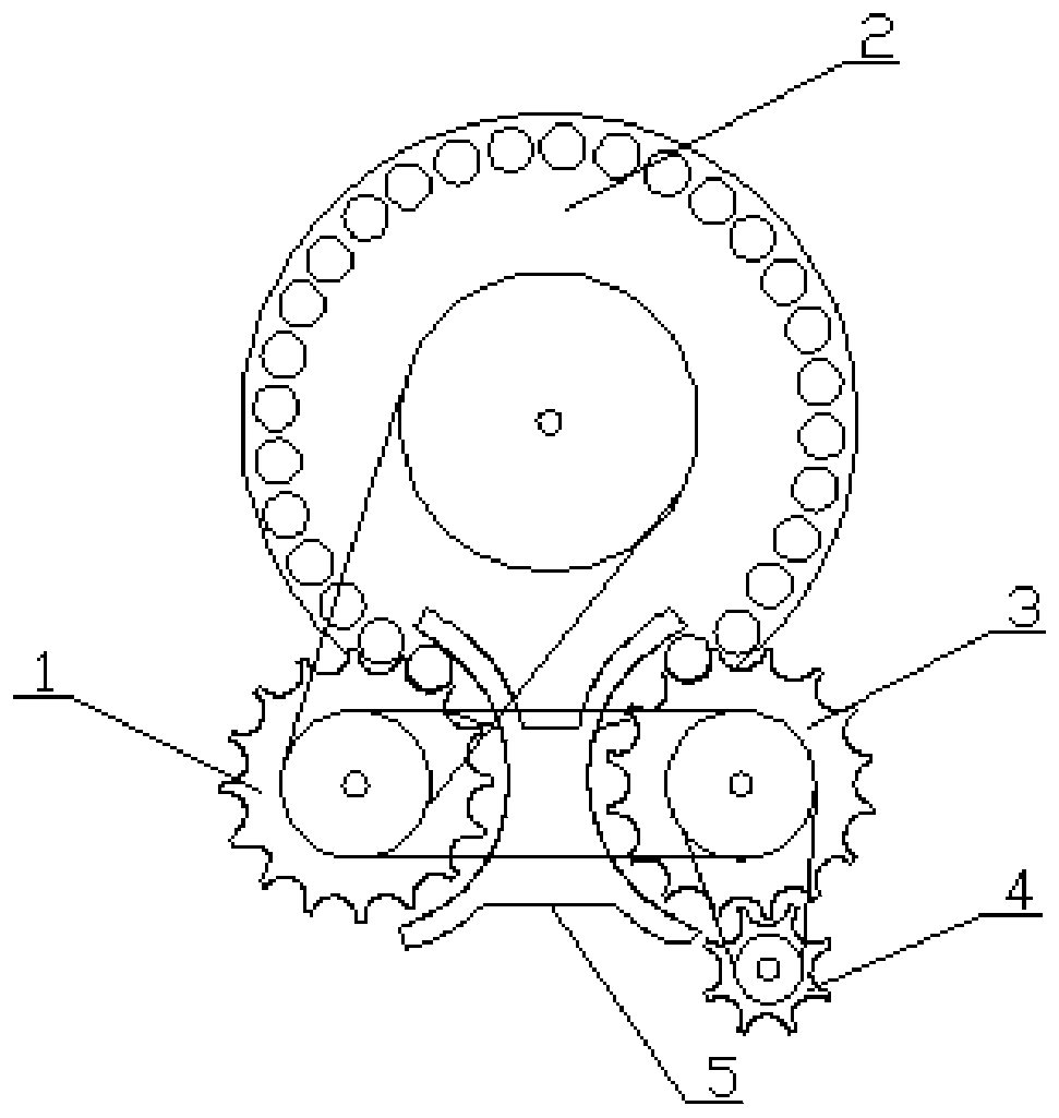
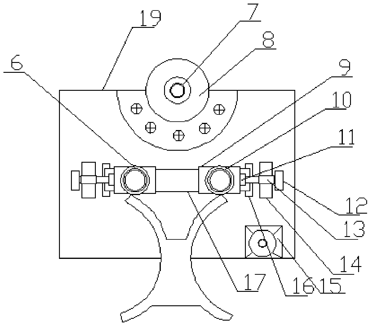
[0023] like Figure 1-3 As shown, a gear transmission system with good usability that is easy to adjust includes an installation side plate 19, a driving motor 15 and an arc-shaped shielding block 5, and the top end of the installation side plate 19 is installed with a second shaft through a limit piece 8 Sleeve 7, the lower end of the No. 2 shaft sleeve 7 is welded with a pad 16, the top of the pad 16 is equipped with a sliding groove 17 through a bolt, and the two ends of the sliding groove 17 are provided with a sliding block 9, and the sliding A No. 3 shaft sleeve 10 and a No. 1 shaft sleeve 6 are respectively installed on the block 9 through bolts. One end of the sliding block 9 is embedded with a bearing 11, and the two ends of the sliding groove 17 are welded with opposite pull blocks 14. The pull block 14 is provided with a threaded sleeve 13, and the bottom end side of the installation side plate 19 is equipped with an active motor 15 through bolts, and the output sha...

Embodiment 2

[0033] like Figure 1-3 As shown, a gear transmission system with good usability that is easy to adjust includes an installation side plate 19, a driving motor 15 and an arc-shaped shielding block 5, and the top end of the installation side plate 19 is installed with a second shaft through a limit piece 8 Sleeve 7, the lower end of the No. 2 shaft sleeve 7 is welded with a pad 16, the top of the pad 16 is equipped with a sliding groove 17 through a bolt, and the two ends of the sliding groove 17 are provided with a sliding block 9, and the sliding A No. 3 shaft sleeve 10 and a No. 1 shaft sleeve 6 are respectively installed on the block 9 through bolts. One end of the sliding block 9 is embedded with a bearing 11, and the two ends of the sliding groove 17 are welded with opposite pull blocks 14. The pull block 14 is provided with a threaded sleeve 13, and the bottom end side of the installation side plate 19 is equipped with an active motor 15 through bolts, and the output sha...


PUM


Abstract

The invention discloses a gear transmission system convenient adjustment and good using capacity. The system comprises a mounting side plate, a driving motor and an arc-shaped shielding block. A second shaft sleeve is mounted at a top end of the mounting side plate through a limiting piece. A cushion block is welded to a lower end of the second shaft sleeve. A sliding groove is formed in a top ofthe cushion block through a bolt; two ends of the sliding groove are sleeved with sliding blocks. Third shaft sleeves and first shaft sleeves are installed on the sliding blocks through bolts. And a bearing is embedded in one end of each sliding block, opposite-pull blocks are welded to the two ends of the sliding groove, threaded sleeves are arranged on the opposite-pull blocks, a driving motor is installed on one side of a bottom end of the mounting side plate through bolts, and an output shaft of the driving motor is connected with a fourth gear. The novel gear transmission system with convenient adjustment and good using capacity is diversified in function, easy to operate, convenient to produce, capable of meeting various requirements in use and suitable for wide application and popularization.

Description

technical field [0001] The invention relates to the technical field of gear transmission, in particular to a gear transmission system that is easy to adjust and has good usability. Background technique [0002] At present, when equipment such as rotary labeling machines, rotary capping machines, and rotary capping machines are in operation, they generally have a transmission system for transmission. [0003] Patent No. CN201811364453.7 discloses a transmission system that uses a belt drive instead of a gear drive. It uses a double-sided synchronous belt for transmission, does not need to be lubricated, and does not have the problem of lubricating oil dripping; due to the belt drive between the gear trains, Therefore, the position of each wheel train can be adjusted according to actual needs without affecting the transmission ratio between the wheel trains; the size of the pulley can be greatly reduced without changing the transmission ratio, and the operating inertia of the ...

Claims


Application Information

Patent Timeline
Patent Type & Authority Applications(China)
IPC IPC(8): F16H7/02F16H7/14
CPCF16H7/02F16H7/14F16H2007/088
Inventor 安宁王飞
Owner 酒泉市四方装备制造有限公司
Why Eureka
Try Eureka