Automatic firing calibration system and calibration method based on thermal imaging telescopic sight

A calibration method and calibration system technology, which is applied in the field of infrared thermal imaging sights, can solve the problems of unreliable accuracy, low efficiency of the shooting effect calibration system, and poor universality, so as to reduce the difficulty of operation, reduce the time for gun calibration, and meet professional requirements. low effect

Active Publication Date: 2020-04-21
北京富吉瑞光电科技股份有限公司
View PDF8 Cites 5 Cited by
  • Summary
  • Abstract
  • Description
  • Claims
  • Application Information

AI Technical Summary

Problems solved by technology

[0004] In order to solve the above problems, the present invention provides an automatic fire efficiency correction system and correction method based on a thermal imaging sight to solve the technical problems of low efficiency, unreliable accuracy and poor universality of the fire effect correction system in the prior art

Method used


Image

  • Automatic firing calibration system and calibration method based on thermal imaging telescopic sight
  • Automatic firing calibration system and calibration method based on thermal imaging telescopic sight
  • Automatic firing calibration system and calibration method based on thermal imaging telescopic sight

Examples


Embodiment 1

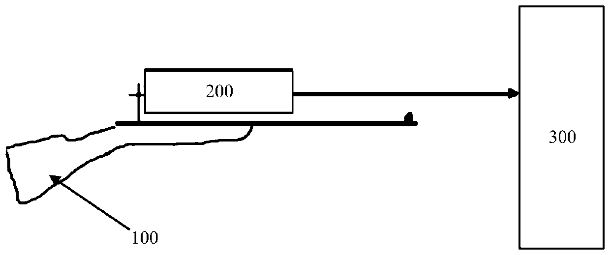
[0044] For the structural schematic diagram of the automatic firing effect correction system based on the thermal imaging sight in this embodiment, please refer to the appendix figure 1 .

[0045] An automatic firing effect correction system based on a thermal imaging sight, comprising a firearm 100, a thermal imaging sight 200 and a thermal target 300, the thermal imaging sight 200 is fixedly mounted on the firearm 100, and the thermal target 300 is mounted on a target at a set distance On the track, target information used to generate specific features for targeting using the thermal imaging sight 200 .

[0046] The thermal imaging sight 200 includes an accelerometer sensor (not shown), which can be used to determine whether the gun has been aimed and stabilized, whether the bullet has been fired, whether it has been fired and stabilized, and the like.

[0047] The thermal imaging sight 200 also includes a processor and a memory, which can acquire and store images in real t...

Embodiment 2

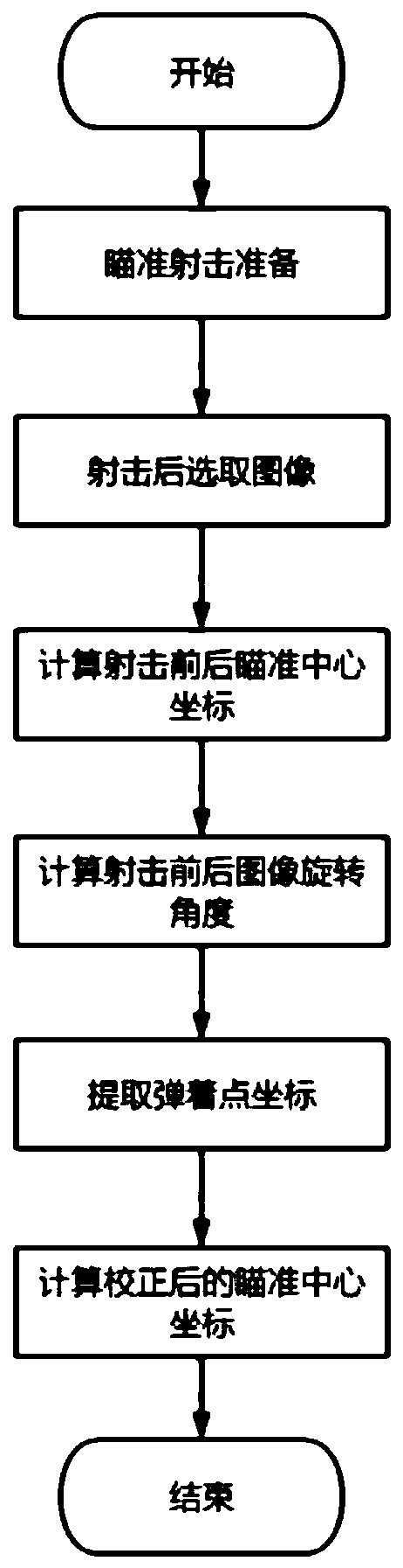
[0049] For the automatic firing effect correction method based on the thermal imaging sight in this embodiment, please refer to the appendix Figure 2-5 .

[0050] An automatic firing effect correction method based on a thermal imaging sight, comprising the following steps:

[0051] Step S100, prepare for aiming and shooting.

[0052] After the user aims at the target, the thermal imaging sight 200 continuously takes pictures of the thermal target 300, and collects the value of the accelerometer corresponding to each frame of the image. When the value of the accelerometer is lower than the first set threshold for a certain period of time and / or when the difference between the image frames is less than the second set threshold, it is assumed that the gun is basically stable, and the system prompts the user whether the target has been aimed. Then the user is prompted to perform the shooting action.

[0053] Step S200, selecting an image after shooting.

[0054] When the fire...


PUM


Abstract

The invention provides an automatic firing calibration system and a calibration method based on a thermal imaging telescopic sight. The calibration method comprises the following steps of, preparationof aimed fire; selection of an image after firing; calculation of coordinates of sighting center before and after firing; calculation of image rotation angle before and after firing; extraction of coordinates of a point of impact; and calculation of the coordinates of sighting center after calibration. According to the calibration system and the calibration method, the gun calibration time of thethermal imaging telescopic sight is reduced, manpower and bullets spent by the gun calibration are reduced, the professional requirement on the gun calibration personnel is low; and the calibration system and the calibration method are good in universality and suitable for a plurality of firearms, and improve gun calibration precision.

Description

technical field [0001] The invention relates to the technical field of infrared thermal imaging sights, in particular to an automatic firing effect correction system and correction method based on thermal imaging sights. Background technique [0002] In order to make the firearm have good shooting accuracy and maintain a good combat state, before the new gun is used for the first time, after replacing or repairing parts that affect the shooting accuracy, or when the shooting accuracy is abnormal during use, such as when aiming After the mirror matching gun is installed and fixed, it is necessary to adjust the zero position to eliminate the inconsistency caused by the connection between the gun body and the scope, and to make the aiming center coincide with the impact point of the bullet. The purpose is to improve the shooting accuracy of firearms. [0003] Most of the existing shooting effect correction methods are manual correction, which takes a long time, and the overall...

Claims


Application Information

Patent Timeline
IPC IPC(8): F41G1/16
CPCF41G1/16
Inventor 季云松陶禹陈德智岳才奇
Owner 北京富吉瑞光电科技股份有限公司
Why Eureka
Try Eureka