Display panel and display device

A technology of display panel and display area, applied in identification devices, optics, instruments, etc., can solve the problems of reducing signal wiring, signal wiring signal interference, etc., saving wiring space, reducing coupling capacitance, and realizing narrow frame design effect

Active Publication Date: 2020-04-21
XIAMEN TIANMA MICRO ELECTRONICS
View PDF15 Cites 2 Cited by
  • Summary
  • Abstract
  • Description
  • Claims
  • Application Information

AI Technical Summary

Problems solved by technology

[0004] In order to realize the narrow frame design of the display panel, it is common practice to arrange the signal traces in the frame area in two different metal film layers, so as to reduce the overall space occupied by the signal traces in the frame area. The signal traces in each metal film layer will inevitably overlap in the direction perpendicular to the plane where the display panel is located, and the overlapping position will easily generate coupling capacitance, which will cause signal interference between the signal traces

Method used


Image

  • Display panel and display device
  • Display panel and display device
  • Display panel and display device

Examples


Embodiment Construction

[0030] Various exemplary embodiments of the present invention will now be described in detail with reference to the accompanying drawings. It should be noted that the relative arrangements of components and steps, numerical expressions and numerical values ​​set forth in these embodiments do not limit the scope of the present invention unless specifically stated otherwise.

[0031] The following description of at least one exemplary embodiment is merely illustrative in nature and in no way taken as limiting the invention, its application or uses.

[0032] Techniques, methods and devices known to those of ordinary skill in the relevant art may not be discussed in detail, but where appropriate, such techniques, methods and devices should be considered part of the description.

[0033] In all examples shown and discussed herein, any specific values ​​should be construed as exemplary only, and not as limitations. Therefore, other instances of the exemplary embodiment may have dif...


PUM


Abstract

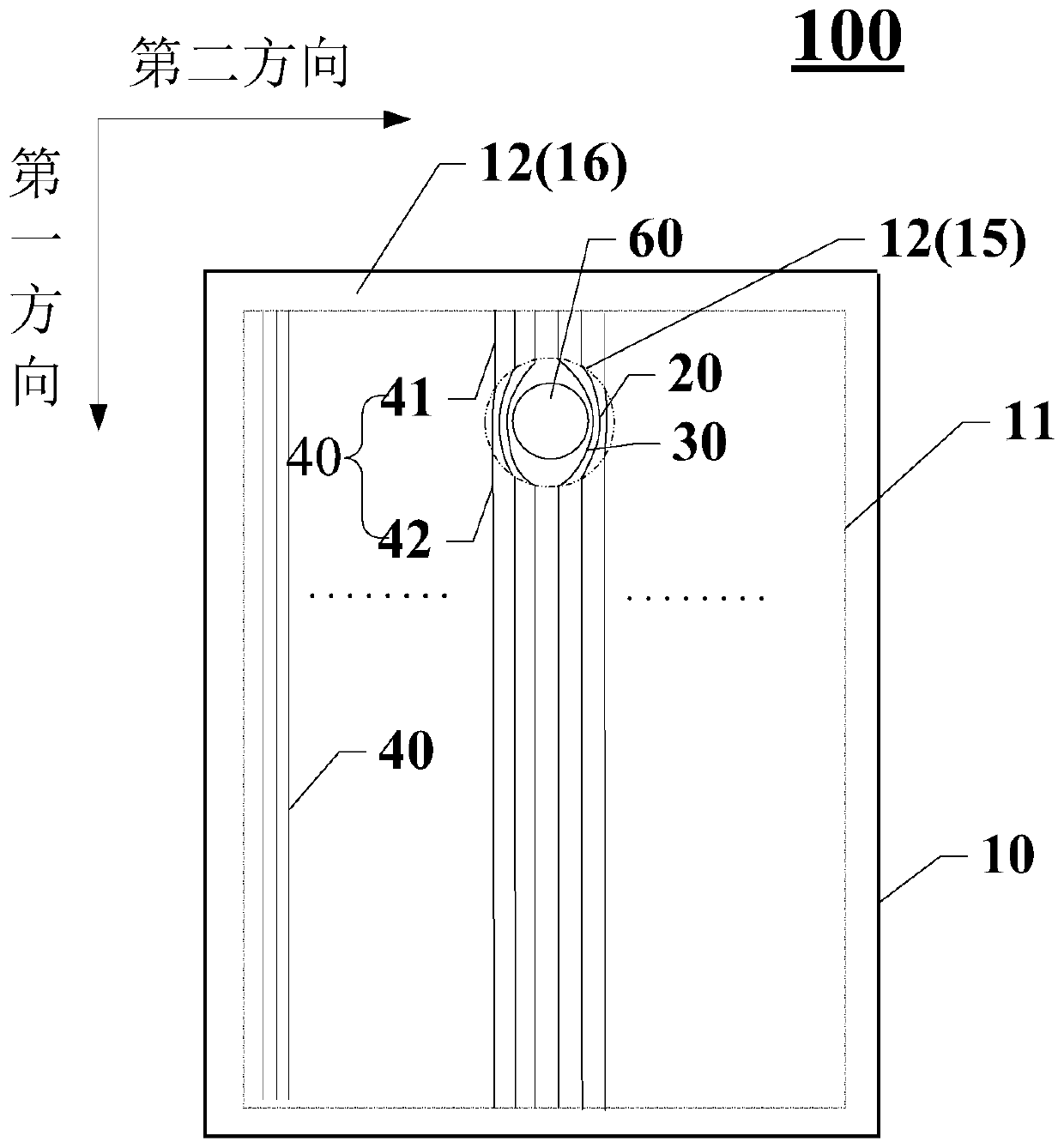
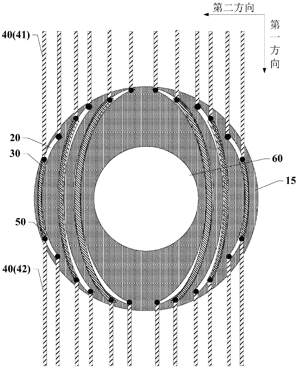
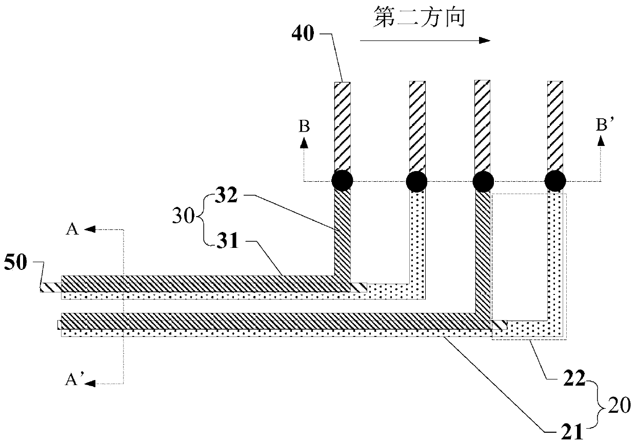
The invention discloses a display panel and a display device, and relates to the technical field of display. The display panel comprises a plurality of first insulated connecting leads and a pluralityof second insulated connecting leads in a non-display area, wherein the first connecting leads are located on a first metal layer; the second connecting leads are located on a third metal layer; thefirst connecting lead comprises a first main body part and a first connecting part connected with the first main body part; the second connecting lead comprises a second main body part and a second connecting part connected with the second main body part; and the first main body part and the second main body part are electrically connected with different first signal lines through the first connecting part and the second connecting part respectively. The display panel also comprises floating parts located in the non-display area and located on a second metal layer. Orthographic projections ofat least one floating part, at least one first main body part and at least one second main body part on the plane where a substrate is located are overlapped. Through the design, the coupling capacitance between the first connecting lead and the second connecting lead can be reduced while the narrow bezel is realized.

Description

technical field [0001] The present invention relates to the field of display technology, and more specifically, to a display panel and a display device. Background technique [0002] With the development of science and technology, the manufacture of display panels is becoming more mature, and more and more display panels are widely used in people's daily life and work, bringing great convenience to people's daily life and work. Existing display panels mainly include liquid crystal display panels (Liquid Crystal Display, LCD), organic light emitting display panels (Organic Light Emitting Diode, OLED), plasma display panels and the like. [0003] In order to increase the display screen and the aesthetics of the appearance of the display device, increasing the display size and resolution, reducing the width of the frame and the thickness of the body has become one of the main research and development directions of technicians in related fields. [0004] In order to realize the...

Claims


Application Information

Patent Timeline
IPC IPC(8): G09F9/00G02F1/1362H01L27/32
CPCG09F9/00G02F1/136286G02F1/13629H10K59/131
Inventor 庄知龙黄建才林昊波
Owner XIAMEN TIANMA MICRO ELECTRONICS
Why Eureka
Try Eureka