
An autonomous current sharing control method for parallel connection of a large number of DC voltage source power modules

A technology of DC voltage source and power module, applied in parallel operation of DC power supply, battery circuit device, current collector, etc., can solve the problems of reduced control effect, entering into fault protection state, increasing the number of modules, etc., to achieve the effect of improving stability

Active Publication Date: 2020-06-16
SHENZHEN WINLINE TECH
View PDF7 Cites 0 Cited by
  • Summary
  • Abstract
  • Description
  • Claims
  • Application Information

AI Technical Summary

Problems solved by technology

[0003] However, as the number of parallel modules increases, the distance between modules also increases. The current sharing method with communication is subject to more restrictions on hardware connections, and the analog control method also requires the use of more additional analog circuit components.
In addition, there are other problems such as transmission delay in the communication current sharing method
[0004] In recent years, a non-communication current sharing digital control method using droop control has been proposed, but the simple droop control using the output current and output voltage as the control quantity can guarantee the response speed, but due to the increase in the number of modules, different module devices lead to different sampling The limitation of accuracy and interference will easily lead to fluctuations in the controlled current, which will reduce the control effect or even cause oscillations, causing the system to lose its stability and enter the fail-safe state. This is one of the reasons why it is difficult to realize the parallel connection of a large number of voltage source modules in this way.

Method used


Image

  • An autonomous current sharing control method for parallel connection of a large number of DC voltage source power modules
  • An autonomous current sharing control method for parallel connection of a large number of DC voltage source power modules

Examples


Embodiment Construction

[0030] In order to make the object, technical solution and advantages of the present invention more clear, the present invention will be further described in detail below in conjunction with the examples. It should be understood that the specific embodiments described here are only used to explain the present invention, not to limit the present invention.

[0031] An autonomous current sharing control method for a large number of DC voltage source power supply modules connected in parallel, comprising the following steps:

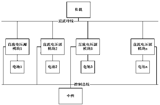
[0032] 1. DC voltage source power supply modules 1, 2, 3, ..., n (n> 3), the input terminals are connected to the batteries respectively, and the output terminals are connected to the same DC bus in parallel operation in DC voltage source mode, and the DC bus is loaded, DC The voltage source power modules 1, 2, 3, ..., n are connected to the same central control through the control bus, and the central control issues a switch command, and the parallel modul...


PUM


Abstract

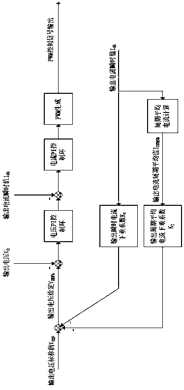
The invention discloses an autonomous current sharing control method for parallel connection of a large number of DC voltage source power modules, which comprises the following steps: 1) For n DC voltage source power modules, the input ends are respectively connected to batteries, and the output ends are in the mode of DC voltage source Parallel connection; 2) Detect and record the instantaneous value of output current and output voltage of each DC voltage source power module; 3) Determine the cycle average value of the output current of each DC voltage source power module; 4) According to the instantaneous value of output current, output The average value of the current cycle, the nominal value of the output voltage of the parallel module, and the calculation of the given value of the voltage loop; Duty ratio to control the output voltage and output current; 6) Repeat steps 2) to 5) to perform current sharing control of the DC voltage source power module. The method of the invention can effectively improve the stability of the parallel system while taking into account the dynamic response performance of the system.

Description

technical field [0001] The invention relates to power circuit control technology, in particular to an autonomous current sharing control method for parallel connection of a large number of DC voltage source power modules. Background technique [0002] At present, when the power level of the system is getting larger and larger, the number of DC voltage source power modules required to be connected in parallel is increasing. If the power modules working in voltage source mode are directly connected in parallel, there will be differences between modules due to hardware differences and control accuracy problems. The current is uneven, so a specific current sharing control method between modules is required. The current sharing methods mainly include two current sharing methods with and without communication between modules, and two implementation methods: analog control mode and digital control mode. [0003] However, as the number of parallel modules increases, the distance bet...

Claims


Application Information

Patent Timeline
Patent Type & Authority Patents(China)
IPC IPC(8): H02J1/10H02J7/00
CPCH02J1/10
Inventor 于洋杨惠坤朱建国
Owner SHENZHEN WINLINE TECH
Learn More