
Heat dissipation solution for wearable equipment

A technology of wearable equipment and equipment, applied in the direction of circuit heating devices, printed circuit components, electrical components, etc., can solve the problems of not being too high surface temperature, scalding consumers, increasing product costs, etc., to meet the heat dissipation and electromagnetic shielding problems , Guarantee normal and stable operation, simple and reasonable structure design

Inactive Publication Date: 2020-04-21
BEIJING CHUANSONG TECH
View PDF0 Cites 2 Cited by
  • Summary
  • Abstract
  • Description
  • Claims
  • Application Information

AI Technical Summary

Problems solved by technology

[0003] Wearable devices pursue beautiful appearance, small size, light weight, etc. At the same time, because the product is close to the human body, the requirements for electromagnetic radiation of the product are relatively strict, especially for the surface temperature of the product not to be too high, which will affect the comfort of the product. , in serious cases may burn consumers
[0004] Most of the current products use shields or heat sinks alone. In this case, heat dissipation and electromagnetic interference cannot be effectively considered.
If the shield is used alone, it cannot effectively solve the heat dissipation problem under the condition of high heating power
Using the heat sink alone can solve the problem of heat dissipation, but the heat sink and the motherboard do not form a closed shielding cavity, which has no shielding effect on electromagnetic signals
[0005] In some cases, the combination of shielding cover and heat sink can meet the heat dissipation and electromagnetic problems, but this kind of use increases the thermal resistance between the heat source and the air, and reduces the heat dissipation effect of the product. So that the performance of the product is subject to certain restrictions
At the same time, due to the increase in the number of parts, the difficulty of material control and material preparation cycle are increased, and the cost of the product will also increase to a certain extent.

Method used


Image

  • Heat dissipation solution for wearable equipment
  • Heat dissipation solution for wearable equipment
  • Heat dissipation solution for wearable equipment

Examples


Embodiment Construction

[0043] Exemplary embodiments of the present disclosure will be described in more detail below with reference to the accompanying drawings. Although exemplary embodiments of the present disclosure are shown in the drawings, it should be understood that the present disclosure may be embodied in various forms and should not be limited by the embodiments set forth herein. Rather, these embodiments are provided for more thorough understanding of the present disclosure and to fully convey the scope of the present disclosure to those skilled in the art.

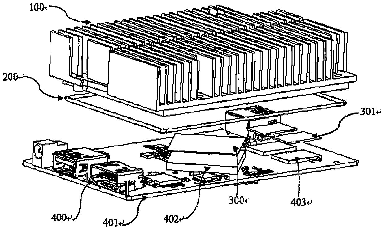
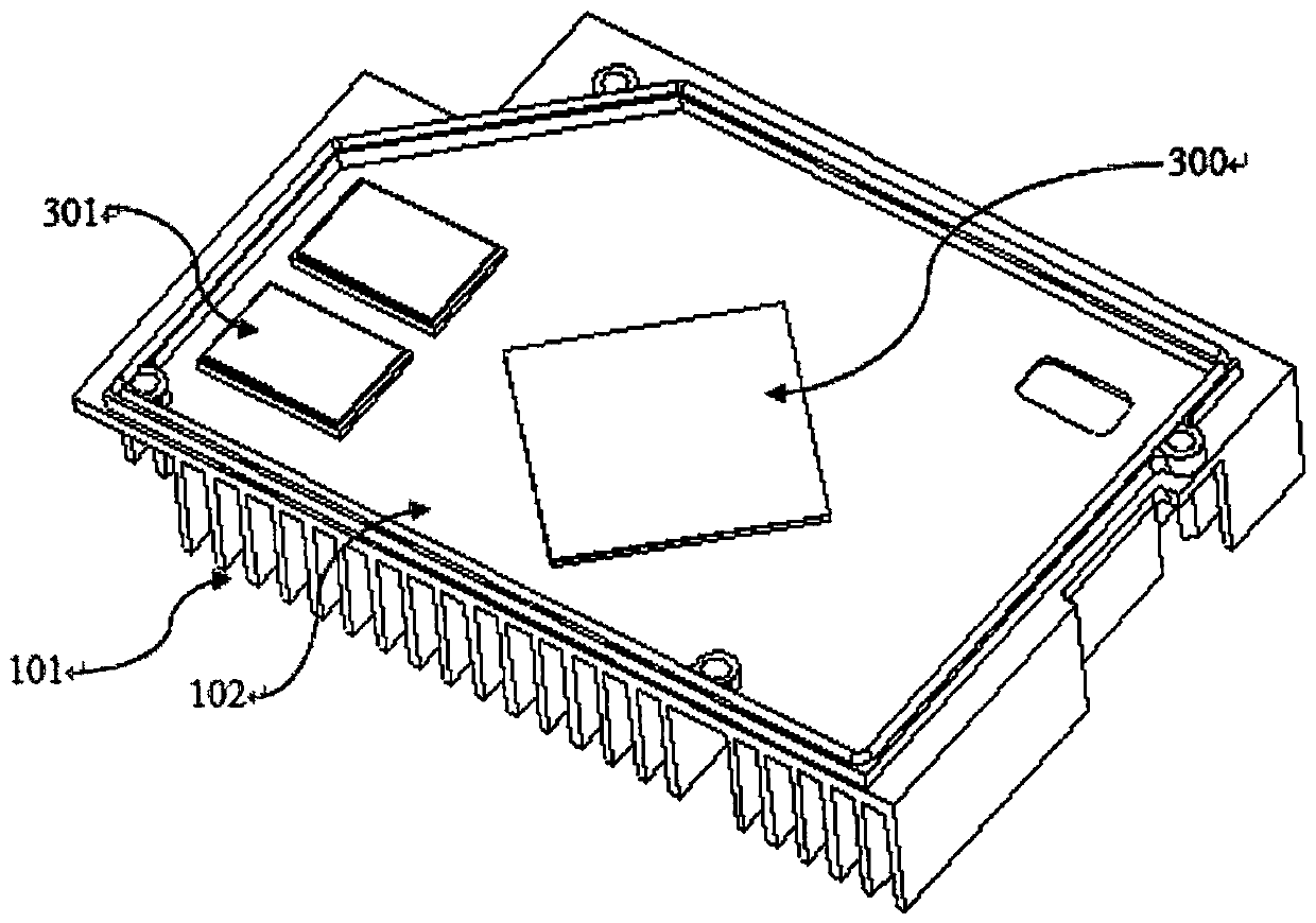
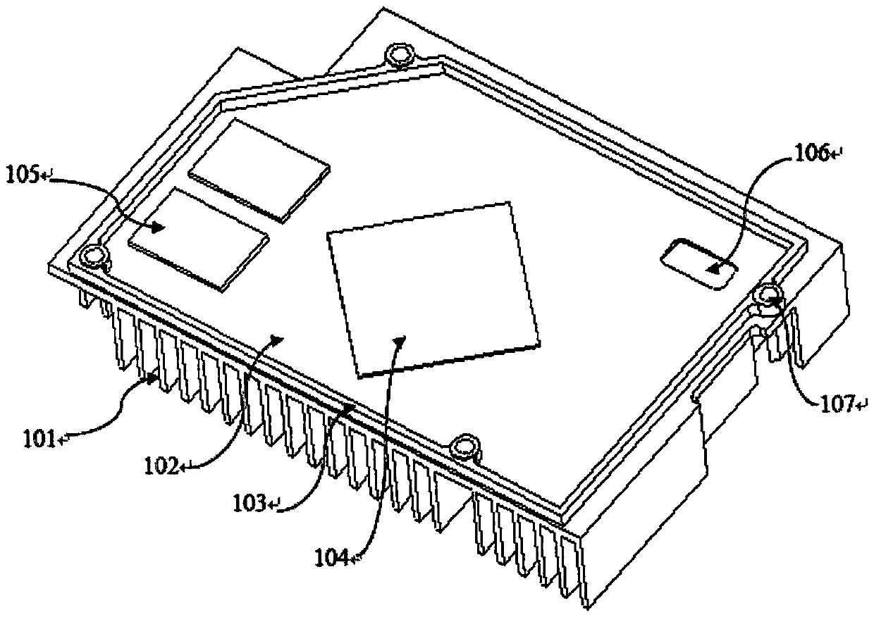
[0044] see figure 1 , figure 2 , figure 1 and figure 2 It is a heat dissipation solution for wearable devices, which includes a heat sink 100 , a shield 200 , a main chip heat conduction material 301 , a memory heat conduction material 302 , and a mainboard 400 as a whole. The main board 400 as a whole includes a circuit board 401 , a main chip 402 , and a memory chip 403 , and the main chip 402 and the memory chip 403 are arr...


PUM


Abstract

The invention relates to a heat dissipation solution of wearable equipment, which comprises a circuit board, and further comprises a heat dissipating sheet, a shielding piece and a heat conduction material, wherein the heat dissipating sheet comprises heat dissipating fins, a heat dissipating sheet bottom plate, a shielding bulge, a structure bulge and a structure groove, wherein the shielding piece is attached to the surface of the shielding bulge on the heat dissipating sheet and is communicated with the heat dissipating sheet and the circuit board at the same time, a closed cavity is formedafter the heat dissipating sheet, the shielding piece and the circuit board are assembled, and an electromagnetic signal source is arranged in the cavity, so that electromagnetic signals generated bythe electromagnetic signal source cannot be radiated to the outside of a product; the heat conduction material is arranged on the surface of the structure bulge and makes contact with the structure bulge and a heat source chip at the same time. According to the heat dissipation solution, the structural design is simple and reasonable, and the heat dissipation and electromagnetic shielding problems of the product are solved at the same time. Meanwhile, due to the fact that the number of parts of the product is reduced, assembling procedures of the product are reduced, and the overall cost of the product is reduced.

Description

technical field [0001] The invention relates to the technical field of smart wearable devices, in particular to a heat dissipation solution for wearable devices. Background technique [0002] With the rapid development of electronic technology and users have put forward higher requirements for product performance and comfort. In order to improve the data processing capability of wearable devices and the low delay of signals, high-performance data processing chips must be used, and the heating power of high-performance chips is relatively high. [0003] Wearable devices pursue beautiful appearance, small size, light weight, etc. At the same time, because the product is close to the human body, the requirements for electromagnetic radiation of the product are relatively strict, especially for the surface temperature of the product not to be too high, which will affect the comfort of the product. , In severe cases, consumers may be scalded. [0004] Current products mostly us...

Claims


Application Information

Patent Timeline
Patent Type & Authority Applications(China)
IPC IPC(8): H05K1/02H05K9/00
CPCH05K1/0209H05K9/0022
Inventor 周朝晖黄磊
Owner BEIJING CHUANSONG TECH
Learn More