
A high temperature resistant industrial Ethernet switch
A high-temperature-resistant, Ethernet technology, which is applied in the direction of casing/cabinet/drawer parts, electrical equipment shell/cabinet/drawer, electrical equipment structural parts, etc., can solve the problem of internal electronic components being damaged by moisture, metal Corrosion of the shell, waste of water resources and other problems, to achieve good shock resistance, increase heat resistance, and increase the effect of power generation current
- Summary
- Abstract
- Description
- Claims
- Application Information
AI Technical Summary
Problems solved by technology
Method used
Image

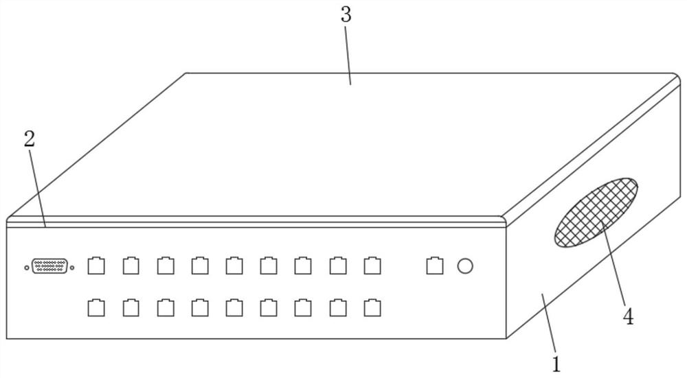
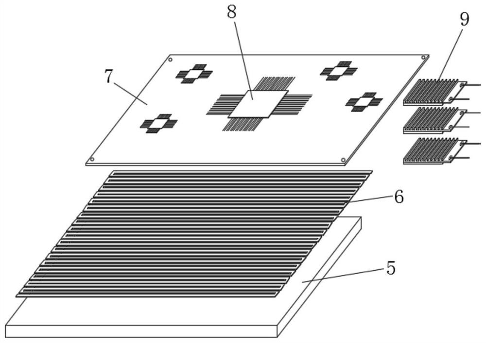
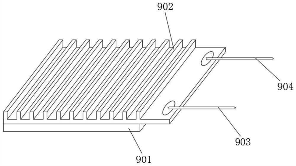
Examples
Embodiment Construction
[0026] The following will clearly and completely describe the technical solutions in the embodiments of the present invention with reference to the accompanying drawings in the embodiments of the present invention. Obviously, the described embodiments are only some, not all, embodiments of the present invention.
[0027] In describing the present invention, it should be understood that the terms "upper", "lower", "front", "rear", "left", "right", "top", "bottom", "inner", " The orientation or positional relationship indicated by "outside", etc. is based on the orientation or positional relationship shown in the drawings, and is only for the convenience of describing the present invention and simplifying the description, rather than indicating or implying that the referred device or element must have a specific orientation, so as to Specific orientation configurations and operations, therefore, are not to be construed as limitations on the invention.
[0028] refer to Figure ...
PUM
 Abstract
Description
Claims
Application Information