Sand and stone crushing equipment for building engineering

A technology for construction engineering and crushing equipment, applied in application, cocoa, grain processing and other directions, can solve the problems of poor primary crushing effect, unfavorable crushing use, inconvenient use, etc. Effect

Inactive Publication Date: 2020-04-24
时守贺
View PDF0 Cites 7 Cited by
  • Summary
  • Abstract
  • Description
  • Claims
  • Application Information

AI Technical Summary

Problems solved by technology

[0004] During the construction of construction projects, it is necessary to continue to crush the sand and gravel to make it finer, which meets the requirements of construction; however, the existing crushing equipment cannot adjust the particle size during grinding and crushing. When sand and

Method used


Image

  • Sand and stone crushing equipment for building engineering
  • Sand and stone crushing equipment for building engineering
  • Sand and stone crushing equipment for building engineering

Examples


Embodiment 1

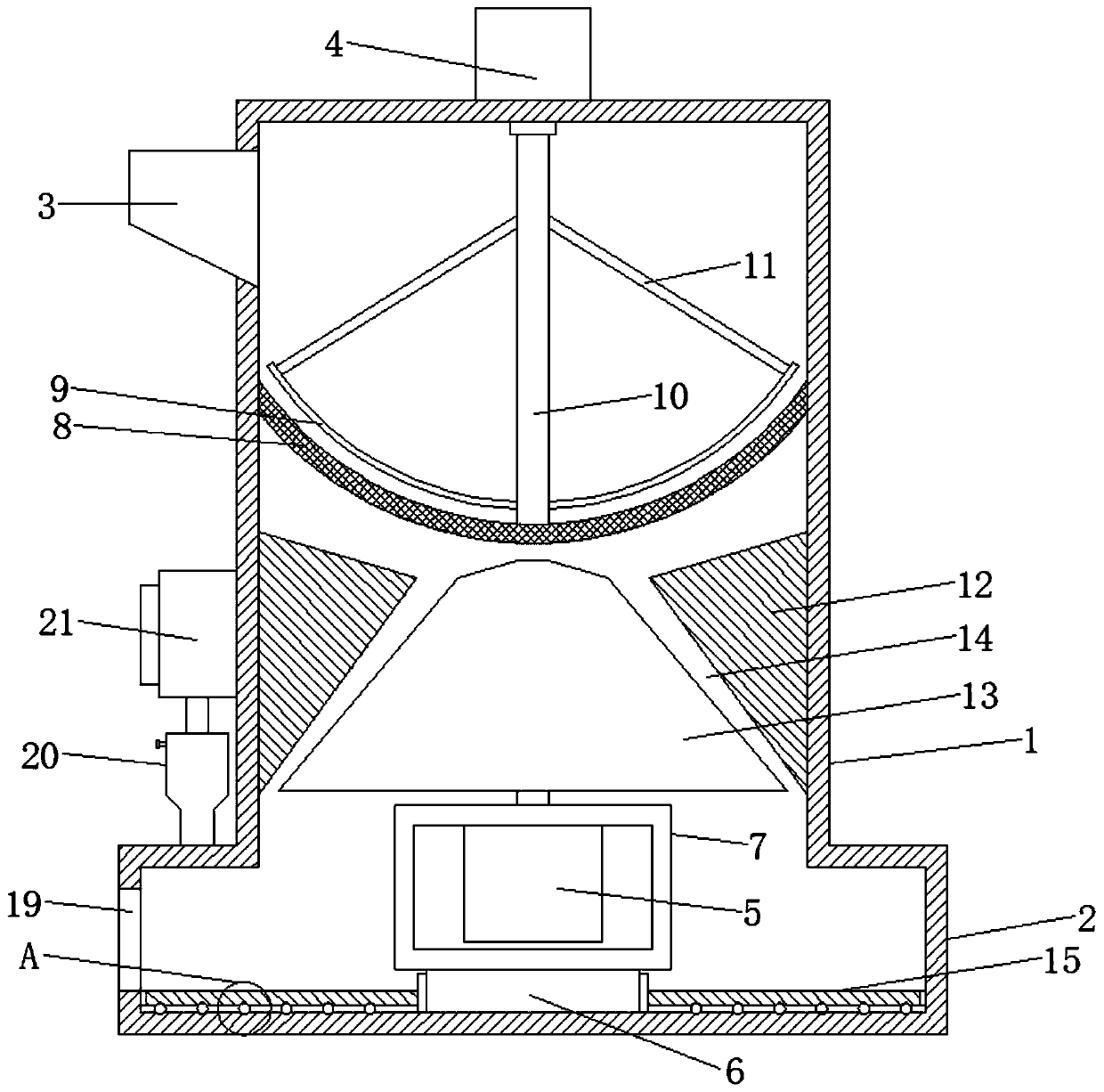
[0024] Please refer to the figure, in the embodiment of the present invention, a sandstone crushing equipment for construction engineering includes a crushing shell 1, a collection box 2, a feed hopper 3, a first motor 4 and a second motor 5; the crushing shell 1 is coaxially fixed on the top of the collection box 2, and the crushing shell 1 is connected to the inside, and the sand falling from the crushing shell 1 enters the collection box 2; the upper end of the side wall of the crushing shell 1 is connected to the feed hopper 3. The sand to be crushed is fed into the crushing shell 1 from the feed hopper 3 .

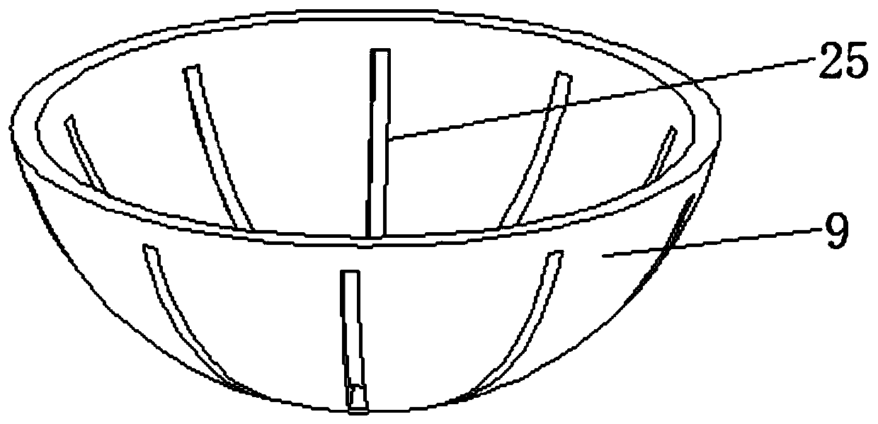
[0025] A primary crushing net 8 with a spherical structure is fixed on the middle part of the crushing shell 1, and the primary crushing net 8 is processed by a stainless steel mesh plate, and the mesh size is selected according to the requirements of the primary crushing; in the crushing shell The top of the body 1 is coaxially fixed with a vertical first motor 4, th...

Embodiment 2

[0029] On the basis of Embodiment 1, the collection box 2 is connected with a purification and dust removal mechanism, which includes a filter cartridge 20, an exhaust fan 21, a filter bag 22, a mounting plate 23, and a support rod 24, and the filter cartridge 20 is connected to the collection box. 2, the filter bag 22 is set in the filter cartridge 20, and the opening of the filter bag 22 communicates with the bottom, so that the air entering the filter cartridge 20 is directly sent into the filter bag 22, and the top of the filter bag 22 is fixedly connected On the horizontal mounting plate 23, the upper end of the filter bag 22 is easy to move. Both sides of the mounting plate 23 are fixedly connected with a support rod 24 that passes through the filter cartridge 20 horizontally, and the support rod 24 is slidably connected with the filter bag 22. By pushing The support rods 24 on both sides shake the top of the filter bag 22 to shake off the filtered dust inside; the top of...


PUM


Abstract

The invention relates to the field of building construction, and particularly discloses sand and stone crushing equipment for building engineering. The equipment comprises a crushing shell, a collection box, a feed hopper, a first motor and a second motor. A primary crushing net of a spherical structure is fixed on the middle part in the crushing shell; a primary grinding disc matched with the primary crushing net in parallel is fixed at the lower end of a rotating shaft, and the primary grinding disc is also of a spherical structure; the center of a grinding fixed seat is provided with a grinding cavity of a circular truncated cone structure, and a grinding roller of a circular truncated cone structure is coaxially arranged in the grinding fixed seat; and the bottom of the grinding rolleris fixedly connected to an output shaft of the second motor, the second motor is fixedly installed on a motor bracket, and a lifting mechanism is fixedly installed on the lower side of the motor bracket. The height of the grinding roller is changed through the arranged lifting mechanism, so that the distance between the grinding roller and the grinding cavity is adjusted, the particle size of crushed sand and stone is changed, adjustment is convenient and rapid, and the application range is wide.

Description

technical field [0001] The invention relates to the field of building construction, in particular to a sandstone crushing equipment for construction engineering. Background technique [0002] Construction engineering refers to the engineering entity formed through the construction of various housing buildings and their ancillary facilities and the installation activities of supporting lines, pipelines and equipment. Among them, "housing construction" refers to projects that have roofs, beams, walls, foundations, and can form internal spaces to meet people's needs for production, living, learning, and public activities. [0003] Sand and gravel refers to a loose mixture of sand grains and gravel. The structure of different sandstones is quite different, some particles are uniform in thickness, and some are of different sizes; Sand and gravel are loose materials, but their particles are generally hard and chemically stable in the surface environment. For sandstone, its weat...

Claims


Application Information

Patent Timeline
IPC IPC(8): B02C7/08B02C2/10B02C23/16B02C23/18
CPCB02C2/10B02C7/08B02C23/16B02C23/18B02C2023/165
Inventor 时守贺
Owner 时守贺
Why Eureka
Try Eureka