An isolated computer main circuit board dust cleaning machine

A main circuit board and computer technology, which is applied in the field of isolated computer main circuit board dust cleaning machine, can solve the problems of dust diffusion, dust diffusion in a large area, affecting the surrounding environment, etc., and achieve the effect of preventing dust diffusion and avoiding large area diffusion

Active Publication Date: 2022-04-05
丸方精密机械(上海)有限公司
View PDF7 Cites 0 Cited by
  • Summary
  • Abstract
  • Description
  • Claims
  • Application Information

AI Technical Summary

Problems solved by technology

[0005] In order to overcome the shortcomings that the existing technology cannot block the blown dust, causing the dust to spread in a large area and affecting the surrounding environment, and the dust contains some harmful impurities, which directly affect people's health, the technical problem of the present invention is: to provide a It is an isolated computer main circuit board dust cleaning machine that can avoid large-scale diffusion of blown dust, does not affect the surrounding environment, and does not affect people's health.

Method used


Image

  • An isolated computer main circuit board dust cleaning machine
  • An isolated computer main circuit board dust cleaning machine
  • An isolated computer main circuit board dust cleaning machine

Examples


Embodiment approach 1

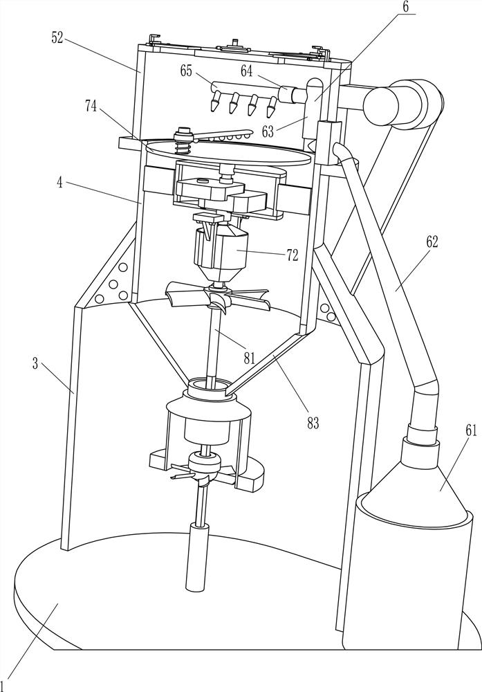
[0026] An isolated computer main circuit board dust cleaning machine, see Figure 1-3 , including a bottom plate 1, a drain valve 2, a water tank 3, a vertical pipe 4, a sealing mechanism 5, an air blowing mechanism 6 and a rotating mechanism 7, a water tank 3 is installed on the top of the bottom plate 1 through bolts, and a drain valve 2 is connected to the lower part of the front side of the water tank 3 The top of the water tank 3 is provided with a vertical pipe 4 by bolts, the vertical pipe 4 is provided with a sealing mechanism 5, the base plate 1 is provided with an air blowing mechanism 6, and the vertical pipe 4 is provided with a rotating mechanism 7.

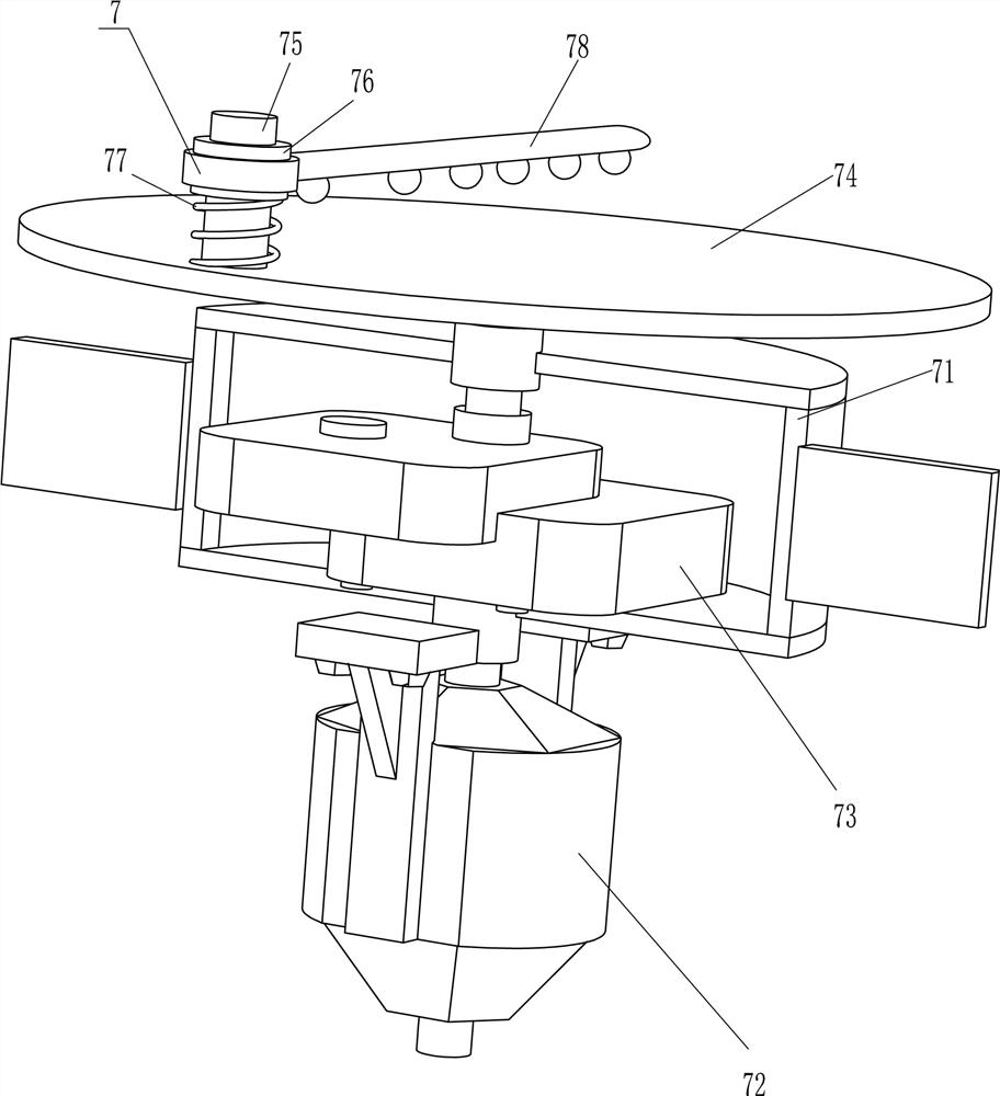
[0027] The sealing mechanism 5 includes a pole 51 and a seal cover 52. The upper part of the water tank 3 right side is connected with a pole 51. The pole 51 is arranged in an inclined manner. The top of the pole 51 is rotatably connected with a seal cover 52. 4 Cover.

[0028] The blowing mechanism 6 includes a boo...

Embodiment approach 2

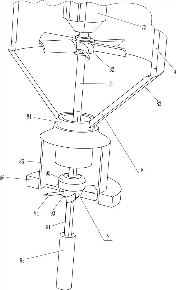
[0035]On the basis of Embodiment 1, see figure 1 , figure 2 , Figure 4 with Figure 5 , also includes an exhaust mechanism 8, the exhaust mechanism 8 includes a rotating rod 81, an exhaust fan 82, a gas gathering cone pipe 83, a guide pipe 84, a slide pipe 85 and a floating ring 86, and on the output shaft below the drive motor 72 A rotary rod 81 is connected through a coupling, and the upper part of the rotary rod 81 is connected with an exhaust fan 82 through a flat key. A slide tube 85 is slidably arranged on the guide tube 84, and a floating ring 86 is connected to the outer lower part of the slide tube 85, and air inlets 87 are evenly spaced on the top of the sealing cover 52 around the circumferential direction.

[0036] Also includes a fusion mechanism 9, the fusion mechanism 9 includes a square rod 91, a connecting sleeve 92, a square hole sleeve 93, a stirring blade 94 and a floating block 95, the bottom end of the rotating rod 81 is connected with a square rod 9...


PUM


Abstract

The invention relates to a dust cleaning machine, in particular to an isolated computer main circuit board dust cleaning machine. The invention provides an isolated computer main circuit board dust cleaning machine which can avoid large-area diffusion of blown dust and does not affect the surrounding environment and people's health. An isolated computer main circuit board dust cleaning machine includes a base plate, a drain valve, a water tank, etc.; the upper side of the base plate is fixedly connected with the water tank. The invention can drive the circuit board to rotate slowly through the rotating mechanism, so that the circuit board can be dedusted in all directions, so that the dedusting is more thorough. Into the water in the water tank, thereby not affecting the surrounding environment, not affecting people's health, the dust can be prevented from floating outward through the exhaust mechanism, so that the dust can be more effectively prevented from spreading.

Description

technical field [0001] The invention relates to a dust cleaning machine, in particular to an isolated computer main circuit board dust cleaning machine. Background technique [0002] Circuit boards are divided into three categories: single-panel, double-panel and multi-layer circuit boards, among which multi-panel is the extension of single-panel. The circuit board is mainly composed of pads, vias, mounting holes, wires, various resistors and capacitors. Used in the computer industry, it plays a vital role. When the circuit board is used for a long time, its surface will be contaminated with a lot of dust. The dust may cause the circuit board to short-circuit and leak electricity, so it is necessary to remove the dust from the circuit board. [0003] Existing circuit board dedusting device, such as the patent with the publication number CN208177931U, discloses a circuit board dedusting device suitable for different sizes, including a box body, the lower surface of the inner ...

Claims


Application Information

Patent Timeline
Patent Type & Authority Patents(China)
IPC IPC(8): B08B5/02B08B13/00B01D47/02
CPCB08B5/023B08B13/00B01D47/02
Inventor 殷金平
Owner 丸方精密机械(上海)有限公司
Why Eureka
Try Eureka