Die pouring system of die casting parts

A technology for parts and molds, applied in the field of mold gating system for die-casting parts, can solve the problems of mold complexity and increase in manufacturing cost, and achieve the effects of low production cost, reduced impact, and reduced gas involvement

Inactive Publication Date: 2020-04-24
ZHANJIANG DENI VEHICLE PARTS
View PDF8 Cites 6 Cited by
  • Summary
  • Abstract
  • Description
  • Claims
  • Application Information

AI Technical Summary

Problems solved by technology

[0004] The industry also uses vacuum die-casting, local extrusion, high-pressure point cooling and other technologies to deal with the problems of pores and shrinkage cavities, but this will lead to a significant increase in mold complexity and manufacturing costs

Method used


Image

  • Die pouring system of die casting parts
  • Die pouring system of die casting parts
  • Die pouring system of die casting parts

Examples


Embodiment 1

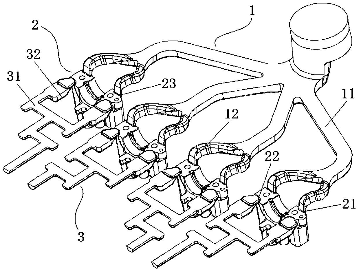
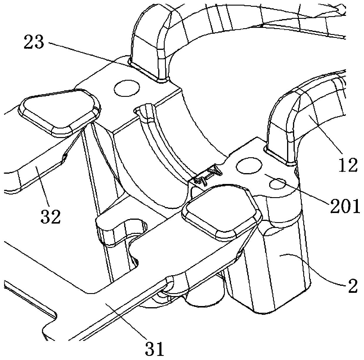
[0033] Such as Figure 1-2 As shown, this embodiment provides a mold pouring and draining system for die-casting parts, which is mainly used in pouring of auto parts;

[0034] The runner system 1 includes several horizontally arranged main runners 11, one end of the main runner 11 is the input end of the molten metal, and the output end of the main runner 11 is provided with several branch runners 12; Wherein, along the conveying direction of the branch runners 12 , the cross-sectional areas of several branch runners 12 gradually become smaller.

[0035] As a preferred solution, when the main runner 11 and the branch runner 12 need to be bent and set, the bends on the main runner 11 and the branch runner 12 are all set with a smooth transition, without Sudden contraction or expansion to avoid pressure loss caused by the collision of molten metal with the side wall of the pipe.

[0036] A number of gates 21 are provided on the parting surface 201 of the molding cavity 2 . In ...

Embodiment 2

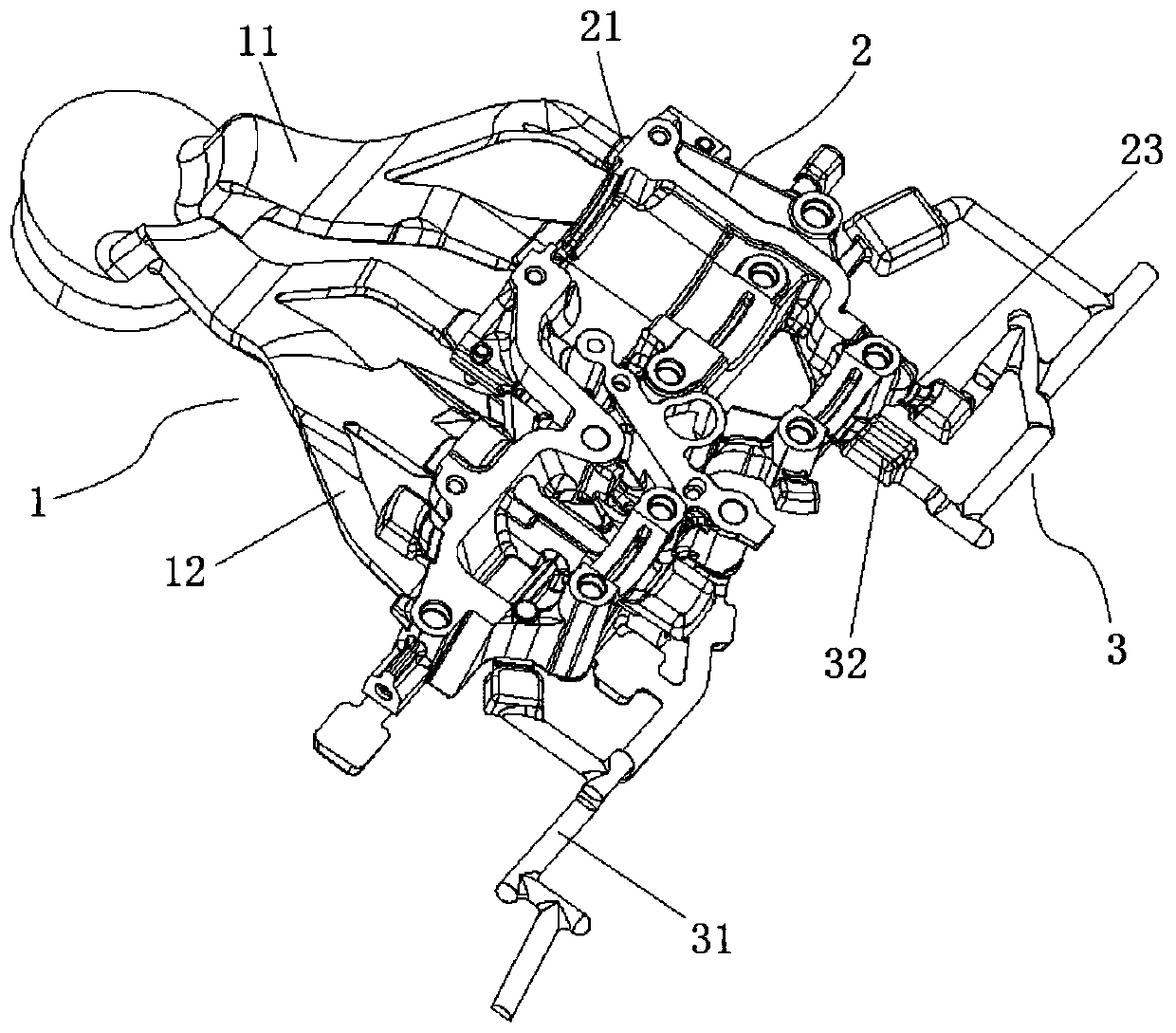
[0045] Such as image 3As shown, a mold pouring system for die-casting parts is provided in this embodiment. The main difference from Embodiment 1 is that this embodiment is mainly applied to the pouring operation of the engine bracket; it includes a runner system 1, a molding cavity 2 and the overflow system 3; during casting, the molten metal is input to the runner system 1, and transported to the molding cavity 2 through the runner system 1 to carry out the casting of the engine bracket, part of the molten metal and the casting process The gas generated in the process is output through the overflow system 3 .

[0046] The runner system 1 includes several main runners 11 and several branch runners 12, the output ends of the main runners 11 and the input ends of the branch runners 12 are connected at an angle, as a preferred solution The angle formed at the connection between the main runner 11 and the branch runner 12 is an obtuse angle; and the connection between the main ...


PUM


Abstract

The invention provides a die pouring system of die-casting parts. The die pouring system comprises a pouring gate system and a forming cavity, the pouring gate system comprises a plurality of main pouring gates, a plurality of branch pouring gates are arranged at the output ends of the main pouring gates, the cross sectional areas of the main pouring gates and / or the branch pouring gates are gradually reduced along the conveying direction of molten metal; a plurality of pouring inlets are formed in the forming cavity, the pouring inlets communicate with the output ends of the branch pouring gates in a one-to-one correspondence mode; along the conveying direction of the molten metal, a plane where the pouring inlets are located serves as the top face of the forming cavity, the molten metaldirectly falls on the bottom face of the forming cavity after entering the forming cavity from the pouring inlets; and the distance value between the setting position of the pouring inlets and the bottom face of the forming cavity comprises the maximum height value of a casting to be formed in the forming cavity. According to the die pouring system of the die-casting parts, the generation of air holes and shrinkage cavities in the inner part of the casting can be reduced, the product quality can be improved, and the production cost can be reduced under the conventional die-casting condition.

Description

technical field [0001] The invention belongs to the technical field of mold pouring and drainage, and in particular relates to a mold pouring and drainage system for die-casting parts. Background technique [0002] High-pressure casting is a process technology that can efficiently manufacture high-quality automotive die-casting parts. High-pressure casting technology is used to manufacture auto parts. The castings are stable in size, high in precision, smooth in surface finish, high in production efficiency and easy to realize automatic production. [0003] There are various small brackets in the car engine, and they support various sports function parts. The structure of the small bracket is simple, and the mold generally adopts the form of split mold with one mold and multiple cavities without sliders, but the wall thickness of the casting is not uniform, and there are deep cavities in the mold, which is easy to produce air holes and shrinkage cavities in the wall thickne...

Claims


Application Information

Patent Timeline
Patent Type & Authority Applications(China)
IPC IPC(8): B22D17/22
CPCB22D17/2272B22D17/22
Inventor 陈佳庄铮易方富
Owner ZHANJIANG DENI VEHICLE PARTS
Why Eureka
Try Eureka