Die pouring system for U-shaped automobile parts

A technology for auto parts and molds, applied in the direction of molds, cores, mold components, etc., can solve problems such as poor feeding effect in the wall thickness area, inconsistent mold temperature, casting ejection deformation, etc., to avoid moving molds Insufficient side wrapping force, low production cost, and guaranteed molding quality

Inactive Publication Date: 2020-07-24
ZHANJIANG DENI VEHICLE PARTS
View PDF8 Cites 1 Cited by
  • Summary
  • Abstract
  • Description
  • Claims
  • Application Information

AI Technical Summary

Problems solved by technology

However, for U-shaped parts, the temperature of the mold on both sides of the U-shaped semi-circle is inconsistent during pouring, the internal quality is different, and the feeding effect of the gate on the wall thickness area is not good.
[0004] In addition, the plan also requires that there be enough thimble tables on the non-processing surface of the product for arranging thimbles, and the clamping force on the side of the movable mold should be greater than that on the side of the fixed mold; otherwise, there will be a great risk of unbalanced ejection, Cause the casting to be ejected, deformed or even broken. For example, when the clamping force of the fixed mold side is greater than that of the movable mold side, the casting will adhere to the fixed mold side, resulting in abnormal production or even crushing the mold.

Method used


Image

  • Die pouring system for U-shaped automobile parts
  • Die pouring system for U-shaped automobile parts
  • Die pouring system for U-shaped automobile parts

Examples


Embodiment 1

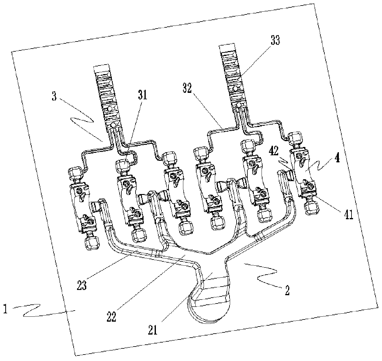
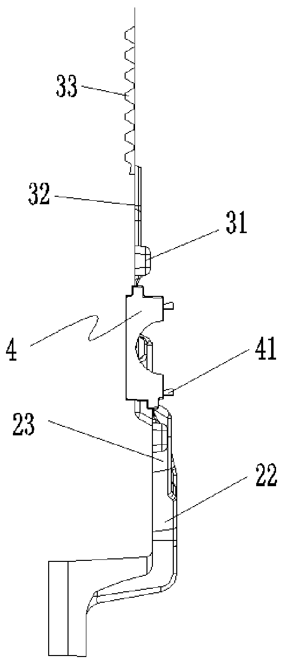
[0032] Such as Figure 1 to Figure 4 As shown, a mold pouring system for U-shaped auto parts is provided in this embodiment, which mainly includes a fixed mold 1, a movable mold (not shown in the figure), a runner system 2, a demoulding mechanism and an overflow System 3.

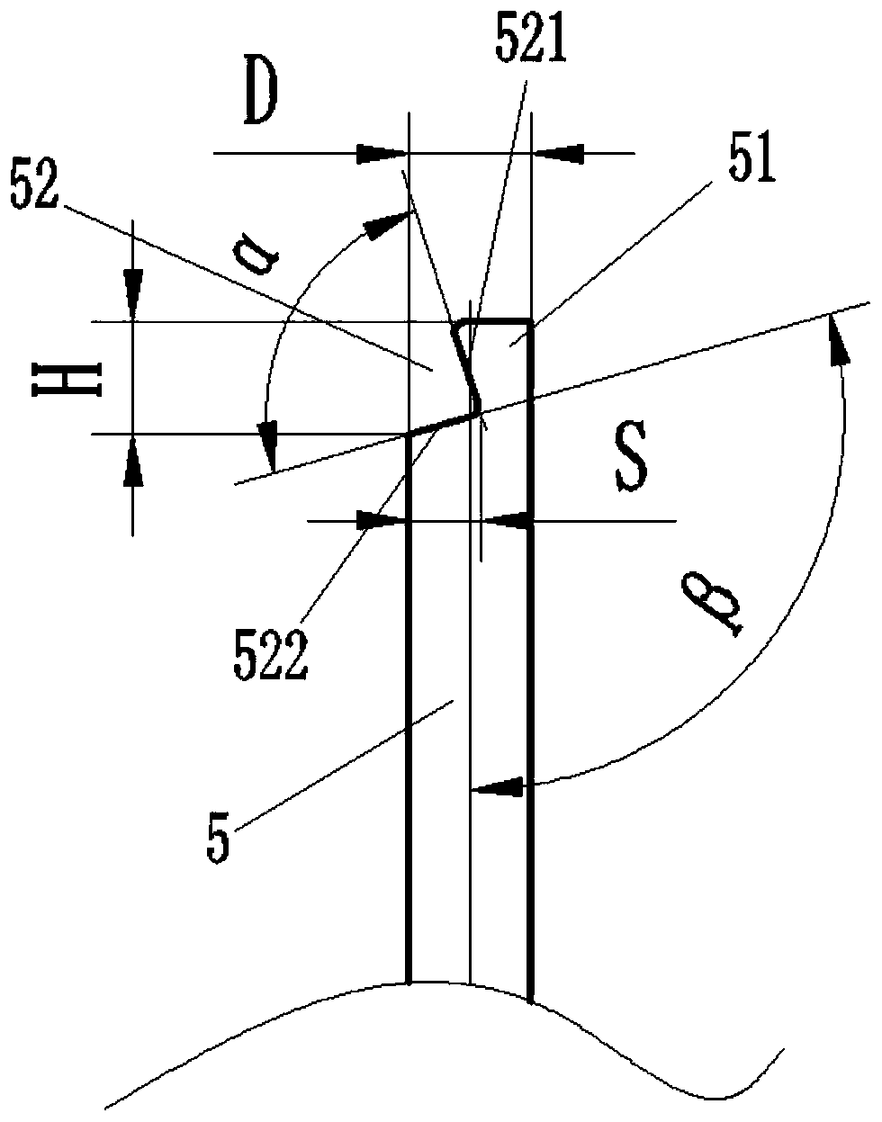
[0033] The fixed mold 1 and the movable mold are covered to form several U-shaped cavities 4, and the U-shaped openings of the U-shaped cavities 4 are arranged toward the movable mold, so that the processing surface of the casting can be aligned with the thimble 5 and, each of the U-forming cavities 4 is arranged vertically, and several U-forming cavities 4 are arranged side by side in a "one" shape.

[0034] The runner system 2 includes a main runner 21, several secondary runners 22 arranged at the output end of the main runner 21, and a branch runner 23 arranged at the output end of the secondary runner 22; wherein, along In the conveying direction of the pouring liquid, the cross-sectional areas of the...


PUM


Abstract

The invention provides a die pouring system for U-shaped automobile parts. The die pouring system for the U-shaped automobile parts mainly comprises a runner system and a demoulding mechanism; the runner system comprises a main runner, a plurality of secondary runners and branch runners; in the conveying direction of pouring liquid, the cross sectional areas of the secondary runners and the branchrunners are gradually reduced; the output ends of the branch runners communicate with an inner pouring gate of a U-shaped forming cavity, and the inner pouring gate is not overlapped with the side wall of the U-shaped forming cavity in the input direction of the inner pouring gate; and the demoulding mechanism comprises a thimble accommodating hole and a thimble, the thimble accommodating hole communicates with the U-shaped forming cavity, a barb part is arranged at one end, close to the U-shaped forming cavity, of the thimble, and the barb part is connected with a casting which is poured into the U-shaped forming cavity in a hooking manner. According to the die pouring system, the casting quality can be effectively improved, the problem of insufficient movable die side tightening force caused by the structure of the product can be avoided, and normal production activities can be ensured.

Description

technical field [0001] The invention belongs to the technical field of mold pouring and drainage, and in particular relates to a mold pouring and drainage system for U-shaped auto parts. Background technique [0002] There are several small brackets in the car engine, which support various sports function parts. Due to the simple structure of the small bracket; in the prior art, the corresponding mold usually adopts a split mold form with one mold and multiple cavities, and the cavity is opened on the side of the movable mold, and the gate is overlapped on the processing surface. [0003] The advantage of this design is that the mold parting is simple. However, for U-shaped parts, mold temperatures on both sides of the U-shaped semi-circle are inconsistent during pouring, internal quality is different, and the gate feeding effect on the wall thickness area is not good. [0004] In addition, the scheme also requires that there be enough thimble tables on the non-processing ...

Claims


Application Information

Patent Timeline
Patent Type & Authority Applications(China)
IPC IPC(8): B22C9/08B22C9/20B22C9/22B22D29/04
CPCB22C9/082B22C9/20B22C9/22B22D29/04
Inventor 陈佳庄铮易方富
Owner ZHANJIANG DENI VEHICLE PARTS
Why Eureka
Try Eureka