
Sintered neodymium-iron-boron hydrogen decrepitation device capable of improving efficiency

A NdFeB high-efficiency technology, applied in the field of sintered NdFeB processing, can solve the problems of equipment hydrogen interruption, difficult pressure monitoring, cumbersome replacement of hydrogen cylinders, etc., and achieve the effect of improving efficiency

Inactive Publication Date: 2021-04-16
GANZHOU FORTUNE ELECTRONICS
View PDF0 Cites 0 Cited by
  • Summary
  • Abstract
  • Description
  • Claims
  • Application Information

AI Technical Summary

Problems solved by technology

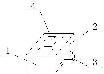
[0005] The technical problem to be solved by the present invention is to provide a sintered NdFeB hydrogen crushing device with improved efficiency. One of the purposes is to have the function of replacing hydrogen cylinders at high speed and fixing them, so as to solve the cumbersome replacement of hydrogen cylinders and cause hydrogen gas inside the equipment. The problem of interruption; another purpose is to solve the problem that the internal pressure of the equipment is not easy to monitor, so as to achieve the effect of real-time monitoring of the specific value of the internal pressure and automatically adjust it, and another purpose is to assist in improving the hydrogen crushing reaction The function of efficiency facilitates the acceleration of the hydrogen crushing reaction, and improves the quality of the final product while maintaining the high-speed hydrogen crushing reaction

Method used


Image

  • Sintered neodymium-iron-boron hydrogen decrepitation device capable of improving efficiency
  • Sintered neodymium-iron-boron hydrogen decrepitation device capable of improving efficiency
  • Sintered neodymium-iron-boron hydrogen decrepitation device capable of improving efficiency

Examples


Embodiment 1

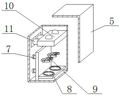
[0030] preferred, such as figure 2 As shown, the hydrogen bottle filling input device 2 includes an induction opening 5, a hydrogen bottle filling base 8, an electromagnetic controller 7, a magnetic adsorption module 9, a pressurized diversion chamber 10, and an anti-leakage protection pipeline 11. The induction opening 5 is covered with hydrogen On the top of the bottle filling input device 2, one end of the electromagnetic controller 7 is fixedly connected to the outer wall of the hydrogen bottle filling base 8, and one end of the magnetic adsorption module 9 is fixedly installed on the inner wall of the hydrogen bottle filling base 8. The top of 10 is fixedly installed inside the hydrogen bottle filling input device 2, the pressurized diversion chamber 10 is located above the hydrogen cylinder filling base 8, and one end of the anti-leakage protection pipeline 11 is fixedly connected inside the pressurized diversion chamber 10.

[0031]In this embodiment, after the hydroge...

Embodiment 2

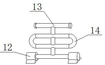
[0033] Such as image 3 As shown, on the basis of embodiment 1, the present invention provides a kind of technical scheme: heat exchange equipment 3 comprises heat production unit 12, heat molecule transfer conduit 13 and heat return pipe 14, and the two ends of heat molecule transfer conduit 13 are all fixed Connected to the inside of the heat production unit 12 , both ends of the heat return pipe 14 are fixedly connected to the inside of the heat molecule transfer conduit 13 .

[0034] Specifically, both the heat molecule transfer conduit 13 and the heat return pipe 14 are fixedly installed inside the heat exchange area 27 , and one end of the polymer extraction pipe 21 is fixedly connected inside the vacuum extraction pipe 26 .

[0035] The above-mentioned embodiments provide that by using the characteristic that the movement speed of high-temperature molecules is faster than that of low-temperature molecules, the heat production unit 12 generates heat and heats the interio...

Embodiment 3

[0037] Such as Figure 4 As shown, on the basis of Embodiment 1 and Embodiment 2, the present invention provides a technical solution: preferably, the bottom of the NdFeB-hydrogen crushing processing chamber 1 is fixedly installed with a crystal storage cavity 20 and a material processing chamber 16, A broken crystal grinder 18 is fixedly installed on the top of the crystal storage cavity 20, and the bottom of the broken crystal grinder 18 is electrically connected to the inside of the energy supply layer 19. The broken crystal grinder 18 is located at the bottom of the material processing chamber 16, and the material processing chamber 16 and the junction of the broken crystal grinder 18 are movably equipped with an induction valve 17.

[0038] Specifically, a hydrogen propeller 15 is fixedly installed at the junction of the hydrogen bottle filling input device 2 and the NdFeB hydrogen crushing treatment chamber 1, and the bottom of the hydrogen propeller 15 is fixedly instal...


PUM


Abstract

The invention discloses a sintered neodymium-iron-boron hydrogen decrepitation device capable of improving efficiency, and relates to the technical field of sintered neodymium-iron-boron processing. The sintered neodymium-iron-boron hydrogen decrepitation device comprises a neodymium-iron-boron hydrogen decrepitation treatment chamber, hydrogen cylinder filling feeding equipment, heat exchange equipment and equipment internal vacuum treatment equipment, wherein the hydrogen cylinder filling feeding equipment is movably installed inside the neodymium-iron-boron hydrogen decrepitation treatment chamber, the heat exchange equipment is fixedly installed at the bottom of the neodymium-iron-boron hydrogen decrepitation treatment chamber, and the bottom of the equipment internal vacuum treatment equipment is fixedly installed at the top of the neodymium-iron-boron hydrogen decrepitation treatment chamber. According to the sintered neodymium-iron-boron hydrogen decrepitation device, through the principle of mutual production between current and magnetic force of an electromagnetic controller, electric power is provided for the electromagnetic controller so as to generate a magnetic field, a hydrogen tank is adsorbed to a hydrogen cylinder filling base, a magnetic force adsorption module also utilizes the characteristic that the magnetic field adsorbs a metal object, hydrogen is injected into a pressurization flow transfer bin, the hydrogen is delivered into the device through an anti-leakage protection pipeline for hydrogen decrepitation, and the hydrogen cylinder is quite convenient to replace.

Description

technical field [0001] The invention relates to a hydrogen crushing device, relates to the technical field of sintered NdFeB processing, in particular to a sintered NdFeB hydrogen crushing device with improved efficiency. Background technique [0002] The hydrogen crushing device is a kind of non-mechanical force that forms ingot or flake rare earth alloy materials into powder, mainly through the reaction of hydrogen gas with rare earth alloys (such as Nd2Fe14B) and using rare earth alloys (such as NdFeB) in the The intergranular fracture and transgranular fracture generated in the process of hydrogen absorption and desorption lead to the pulverization of rare earth alloys, forming an embrittlement and crushing process, and thus obtaining a certain particle size of rare earth alloy powder. There are following problems at prior art: [0003] 1. The hydrogen crushing device has the problem that the hydrogen supply is not fast enough. When dealing with a large amount of NdFeB,...

Claims


Application Information

Patent Timeline
Patent Type & Authority Applications(China)
IPC IPC(8): B22F9/02H01F1/057
Inventor 剧智华钟春燕刘滨蔡小勇庞再升喻玺
Owner GANZHOU FORTUNE ELECTRONICS
Learn More