Angle steel welding and positioning device and welding equipment using positioning device

A welding positioning and welding equipment technology, applied in welding equipment, auxiliary welding equipment, welding/cutting auxiliary equipment, etc., can solve problems such as bowing, and achieve the effect of improving welding quality

Pending Publication Date: 2020-04-24
HENAN MINE CRANE
View PDF1 Cites 2 Cited by
  • Summary
  • Abstract
  • Description
  • Claims
  • Application Information

AI Technical Summary

Problems solved by technology

[0006] The purpose of the present invention is to provide an angle steel welding positioning device to solve the problem of "bow head" of the angle steel in the process of being welded to the web in the prior art; the purpose of the present invention is also to provide a welding positioning device using the above angle steel Advanced angle steel welding equipment to improve the quality of angle steel welding

Method used


Image

  • Angle steel welding and positioning device and welding equipment using positioning device
  • Angle steel welding and positioning device and welding equipment using positioning device
  • Angle steel welding and positioning device and welding equipment using positioning device

Examples


specific Embodiment 1

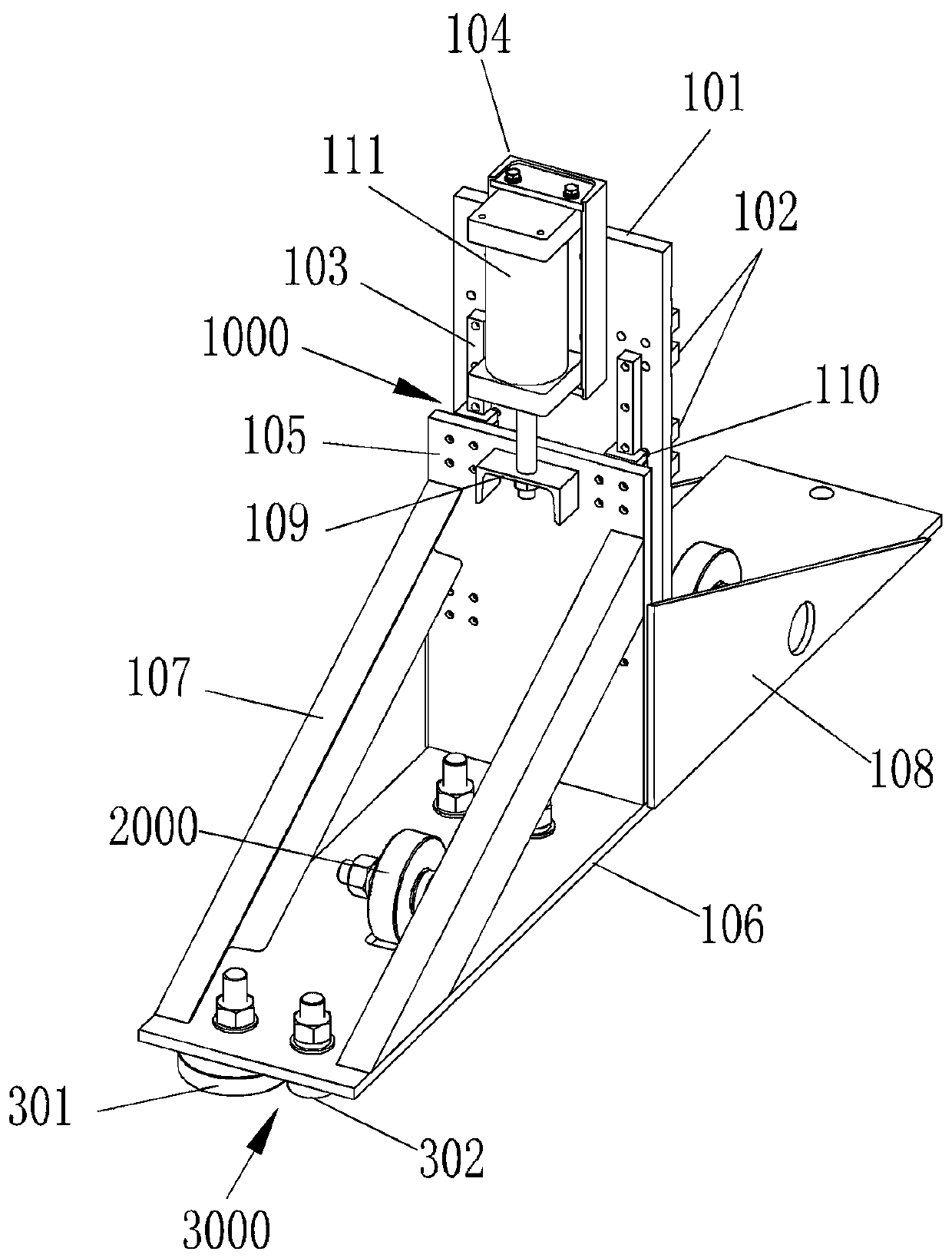
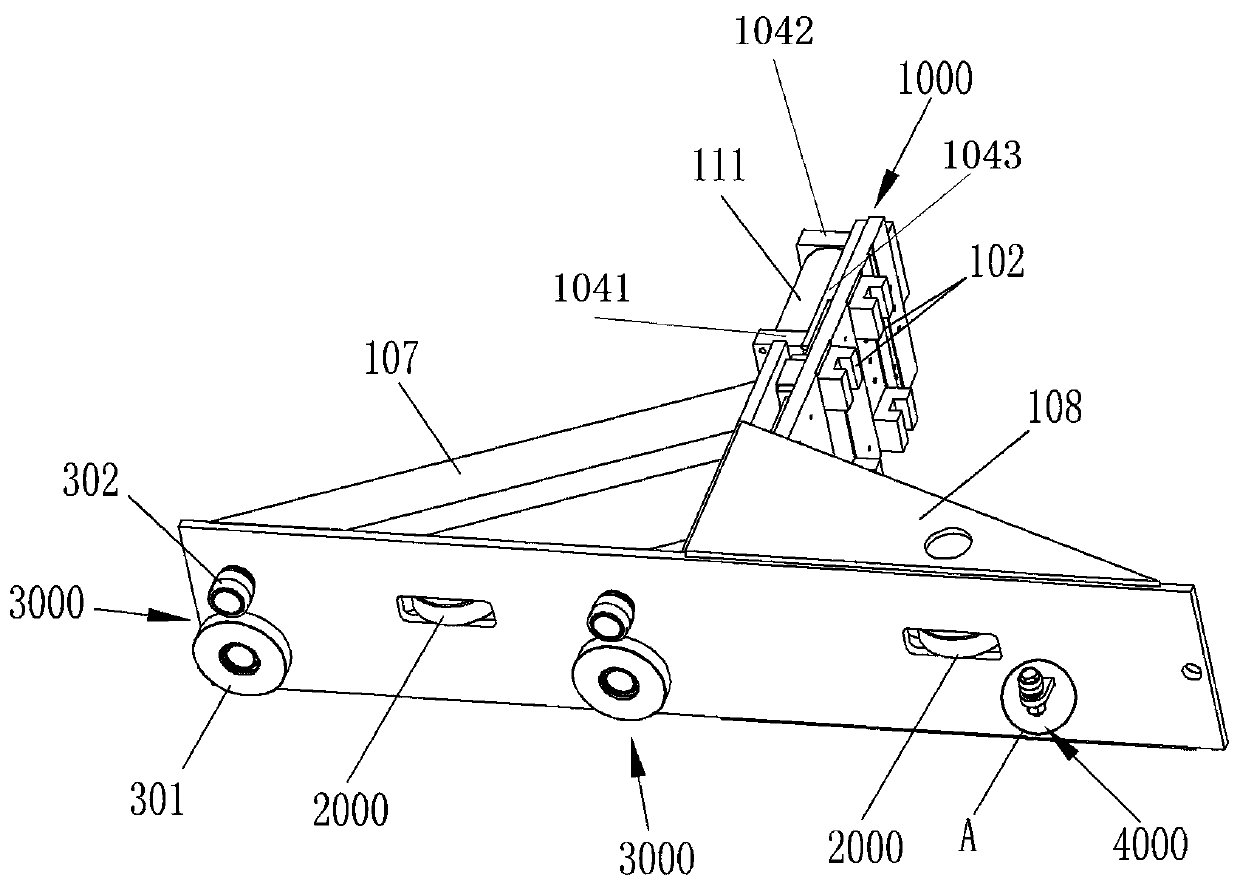
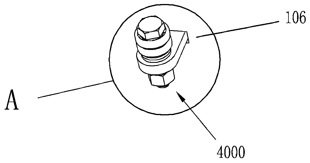
[0036] Such as Figure 1-7 As shown, in this embodiment, the main components of the angle steel welding positioning device include a mounting frame 1000 , a pressing wheel 2000 , a clamping wheel set 3000 and a centralizing body 4000 .

[0037] The mounting frame 1000 is a combined frame, including a fixed part, a movable part and a pressing driving device installed between the fixed part and the movable part. The fixed part includes a base plate 101 , a base plate slider 102 , a movable plate slide rail 103 , and a cylinder seat 104 . The movable part comprises a movable plate 105, a base plate 106, a reinforcing brace 107, a rib plate 108, a cylinder connector 109 and a movable plate slider 110, and the pressing driving device is an air cylinder 111.

[0038] The substrate slider 102 is installed on the back of the substrate 101 and has upper and lower layers. Each substrate slider 102 is provided with a chute for installing the substrate 101 on the door frame 501 of the tr...

specific Embodiment 2

[0046] The difference between this embodiment and Embodiment 1 of the angle steel welding positioning device is that in this embodiment, the stabilizer adopts a slider instead of a bearing. As mentioned above, the function of the centralizer is to hold the horizontal part of the angle steel and prevent it from falling down. In order to meet this requirement, in other embodiments, the centralizer can actually use a fixed-axis rolling body such as a general roller, or a universal Universal rolling elements such as wheels.

specific Embodiment 3

[0048] The difference between this embodiment and Embodiment 1 of the angle steel welding positioning device is that in this embodiment, the centralizer and the corresponding (relatively close) pinch wheel are staggered in the longitudinal direction, and in other embodiments, the It can also be aligned with the centralizing body in the longitudinal direction, and the centralizing body and the pressing wheel can be arranged in a horizontal direction. Together with the centralizing body and the pressing wheel, the unevenness on the horizontal part of the angle steel can be flattened.


PUM


Abstract

The invention relates to the field of crane beam welding equipment, in particular to an angle steel welding and positioning device and welding equipment using the positioning device. The angle steel welding equipment comprises a trolley; the angle steel welding and positioning device is arranged on the trolley and comprises an installation frame; pinch rollers and a clamping wheel group are arranged on the installation frame; the angle steel welding and positioning device further comprises a centralizer body; and the centralizer body is arranged on the installation frame and is used for supporting a part, parallel to a web, of angle steel to be welded so as to prevent the top part of the part, parallel to the web, of the angle steel to be welded from inclining downwards. In the angle steelwelding equipment provided by the invention, according to the angle steel welding and positioning device, the centralizer body is added on the installation frame and can support the part, parallel tothe web, of the angle steel when the angle steel is welded to the web, and the part, parallel to the web, of the angle steel is prevented from inclining downwards through a blocking way, so that theproblem that the angle steel is lowered down in the process of being welded to the web can be solved, and the angle steel welding quality is improved.

Description

technical field [0001] The invention relates to the field of crane beam welding equipment, in particular to an angle steel welding positioning device and welding equipment using the positioning device. Background technique [0002] The main girder of the crane includes a cover plate, a bottom plate and two webs, and the two webs are arranged at intervals in the left and right directions and connected between the cover plate and the bottom plate. In the prior art, in order to ensure the structural strength of the main girder, the web is required to have a certain camber in the up and down direction. At the same time, in order to control the waviness of the web during the welding process of the main girder, a certain amount of camber is welded and fixed on the web. Angle steel, and the camber of the angle steel is required to be consistent with the camber of the corresponding web. Among the two arms of the angle steel, one is welded vertically to the web plate surface to form ...

Claims


Application Information

Patent Timeline
IPC IPC(8): B23K37/04
CPCB23K37/04B23K37/0443
Inventor 邵东亮李峰武高轩崔红哲刘欢郑沛
Owner HENAN MINE CRANE
Why Eureka
Try Eureka