Measuring equipment for balance coefficient of elevator
A technology of balance coefficient and measuring device, applied in transportation, packaging, elevators, etc., can solve the problems of difficulty in obtaining elevator balance coefficient, time-consuming and laborious, low efficiency, etc., to avoid inaccurate measurement data, improve structural stability, and improve The effect of accuracy
- Summary
- Abstract
- Description
- Claims
- Application Information
AI Technical Summary
Problems solved by technology
Method used
Image

Examples
Embodiment 1
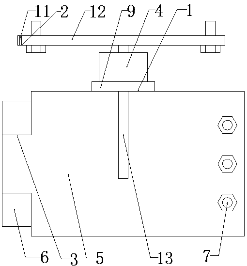
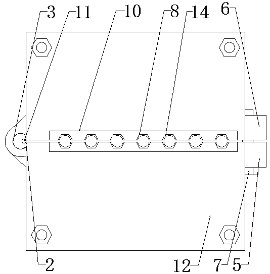
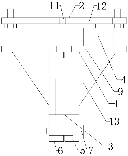
[0026] as attached Figure 1-5 As shown, an elevator balance coefficient measuring device includes a rope clamp weighing device 1 and a fixed seat 2. The rope clamp weighing device 1 is composed of a wire rope clamp 3 and a pressure sensor 4. The upper side of the wire rope clamp 3 is A pressure sensor 4 is fixedly installed, and a fixing base 2 is arranged above the pressure sensor 4 .
[0027] The wire rope clamp 3 includes a splint 5 and a base plate 6 whose left ends are hinged together through a shaft, and a fastening bolt 7 arranged at the right end of the splint 5 and the base plate 6, and a rope groove is provided on the middle contact surface of the splint 5 and the base plate 6 8. The upper side of the splint 5 and the base plate 6 is fixedly connected with a connecting plate 9 vertical to the splint 5 and the base plate 6 , and the pressure sensor 4 is installed on the upper side of the connecting plate 9 .
[0028] The fixed seat 2 is installed on the elevator bas...
Embodiment 2
[0037] as attached Figure 6 As shown, an elevator balance coefficient measuring device includes a rope clamp weighing device 1 and a fixed seat 2. The rope clamp weighing device 1 is composed of a wire rope clamp 3 and a pressure sensor 4. The lower side of the wire rope clamp 3 is A pressure sensor 4 is fixedly installed, and a fixing seat 2 is arranged below the pressure sensor 4 .
[0038] The wire rope clamp 3 includes a splint 5 and a base plate 6 whose left ends are hinged together through a shaft, and a fastening bolt 7 arranged at the right end of the splint 5 and the base plate 6, and a rope groove is provided on the middle contact surface of the splint 5 and the base plate 6 8. The lower side of the splint 5 and the base plate 6 is fixedly connected with a connecting plate 9 vertical to the splint 5 and the base plate 6 , and the pressure sensor 4 is installed on the lower side of the connecting plate 9 .
[0039] Described fixing seat 2 is installed on the upper s...
PUM
 Abstract
Description
Claims
Application Information
 - Generate Ideas
- Intellectual Property
- Life Sciences
- Materials
- Tech Scout
- Unparalleled Data Quality
- Higher Quality Content
- 60% Fewer Hallucinations
Browse by: Latest US Patents, China's latest patents, Technical Efficacy Thesaurus, Application Domain, Technology Topic, Popular Technical Reports.
© 2025 PatSnap. All rights reserved.Legal|Privacy policy|Modern Slavery Act Transparency Statement|Sitemap|About US| Contact US: help@patsnap.com