
Pile driving force adjusting device and hydraulic piling hammer

A technology of hydraulic piling hammer and force adjustment, which is applied in the direction of sheet pile walls, buildings, and foundation structure engineering, etc., to achieve the effects of solving large heat generation, improving energy profit margin, and solving damage

Active Publication Date: 2021-08-31
韶关市伟光液压油缸有限公司
View PDF0 Cites 0 Cited by
  • Summary
  • Abstract
  • Description
  • Claims
  • Application Information

AI Technical Summary

Problems solved by technology

At present, there is no special striking force setting device for hydraulic piling hammers. Generally, the lifting height of the heavy hammer is controlled to control the impact speed of the heavy hammer hitting the pile cap. Roughly change the time t for controlling the hitting pile cap. to roughly adjust the actual piling force

Method used


Image

  • Pile driving force adjusting device and hydraulic piling hammer
  • Pile driving force adjusting device and hydraulic piling hammer
  • Pile driving force adjusting device and hydraulic piling hammer

Examples


Embodiment Construction

[0014] The technical solutions in the embodiments of the present application will be clearly and completely described below in conjunction with the drawings in the embodiments of the present application. Apparently, the described embodiments are only some of the embodiments of this application, not all of them. Based on the embodiments in this application, all other embodiments obtained by those skilled in the art without making creative efforts belong to the scope of protection of this application.

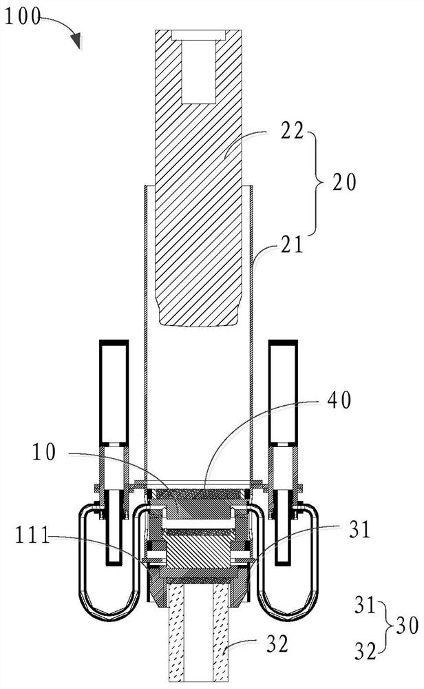
[0015] The embodiment of the present application provides a piling force adjusting device 10 and a hydraulic piling hammer 100 .

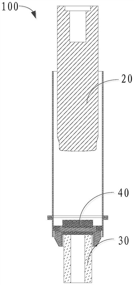
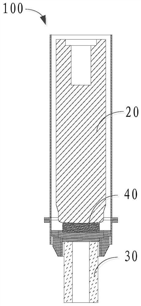
[0016] A hydraulic piling hammer 100 is provided in related embodiments of the present application, please refer to figure 1 and figure 2 shown. figure 1 It is a schematic diagram of the rising state of the hydraulic piling hammer 100 . figure 2 It is a schematic diagram of the state of the hydraulic piling hammer 100 during piling. Wherein, th...


PUM


Abstract

An embodiment of the present application provides a piling force adjustment device and a hydraulic piling hammer. The piling force adjustment device includes: a mounting frame, a force transmission cylinder, and an oil-gas booster cylinder. The force transmission cylinder is installed on the force transmission cylinder. The force transmission cylinder is connected with the oil-air booster cylinder through a hydraulic oil pipe, and the oil-air booster cylinder is used to adjust the pressure of the force transfer cylinder. The force transmission cylinder is connected with the oil-air booster cylinder. The cylinder is used to adjust the piling force of the hydraulic piling hammer. The embodiment of the present application can adjust the piling force of the hydraulic piling hammer, thereby improving the service life of the hydraulic piling hammer.

Description

technical field [0001] The present application relates to the field of engineering machinery, in particular to a piling force adjusting device and a hydraulic piling hammer. Background technique [0002] The hydraulic piling hammer is a device that uses the heavy hammer to drop quickly at a certain height and then hit the pile cap. It mainly uses the conversion principle of momentum and impulse (F=V m / t) to convert the momentum of the heavy hammer into A machine of force that strikes a pile. Among them, V is the falling speed of the weight, m ​​is the mass of the weight, and t is the time when the weight hits the pile cap. On the premise that the weight of the hammer is constant, the magnitude of the force F to hit the pile is related to the speed V of the hammer and the time t of hitting the pile cap. [0003] Because the impact force that a pile of one specification can withstand is limited, it is necessary to adjust the piling force transmitted from the heavy hammer of ...

Claims


Application Information

Patent Timeline
Patent Type & Authority Patents(China)
IPC IPC(8): E02D7/14E02D7/10
CPCE02D7/10E02D7/14
Inventor 梁曲考陈伟光
Owner 韶关市伟光液压油缸有限公司
Learn More