Sludge removing device

A technology for removing equipment and silt, which is applied in earth movers/shovels, mechanically driven excavators/dredgers, construction, etc. It can solve the problem that the bottom mud cannot be stirred when the reamer cuts the mud, and the dredging operation is difficult to carry out smoothly, etc. question

Inactive Publication Date: 2020-04-24
柯世苑
View PDF5 Cites 0 Cited by
  • Summary
  • Abstract
  • Description
  • Claims
  • Application Information

AI Technical Summary

Problems solved by technology

[0003] However, when the above-mentioned existing silt removal device wants to move the position of the dredging operation, it is necessary to repeatedly lift and lower the multiple groups of anchor spindles to position the floating platform, and if it encounters a strong wind and wave, the floating platform will often be damaged due to the wind and waves. Vigorous shaking, which in turn affects the dredging of the reamer suction head and cannot stir the bottom mud, making it difficult to carry out the dredging operation smoothly

Method used


Image

  • Sludge removing device
  • Sludge removing device
  • Sludge removing device

Examples


Embodiment Construction

[0024] In order to make the above-mentioned and other objects, features and advantages of the present invention more comprehensible, the preferred embodiments of the present invention are specifically cited below, together with the accompanying drawings, and are described in detail as follows:

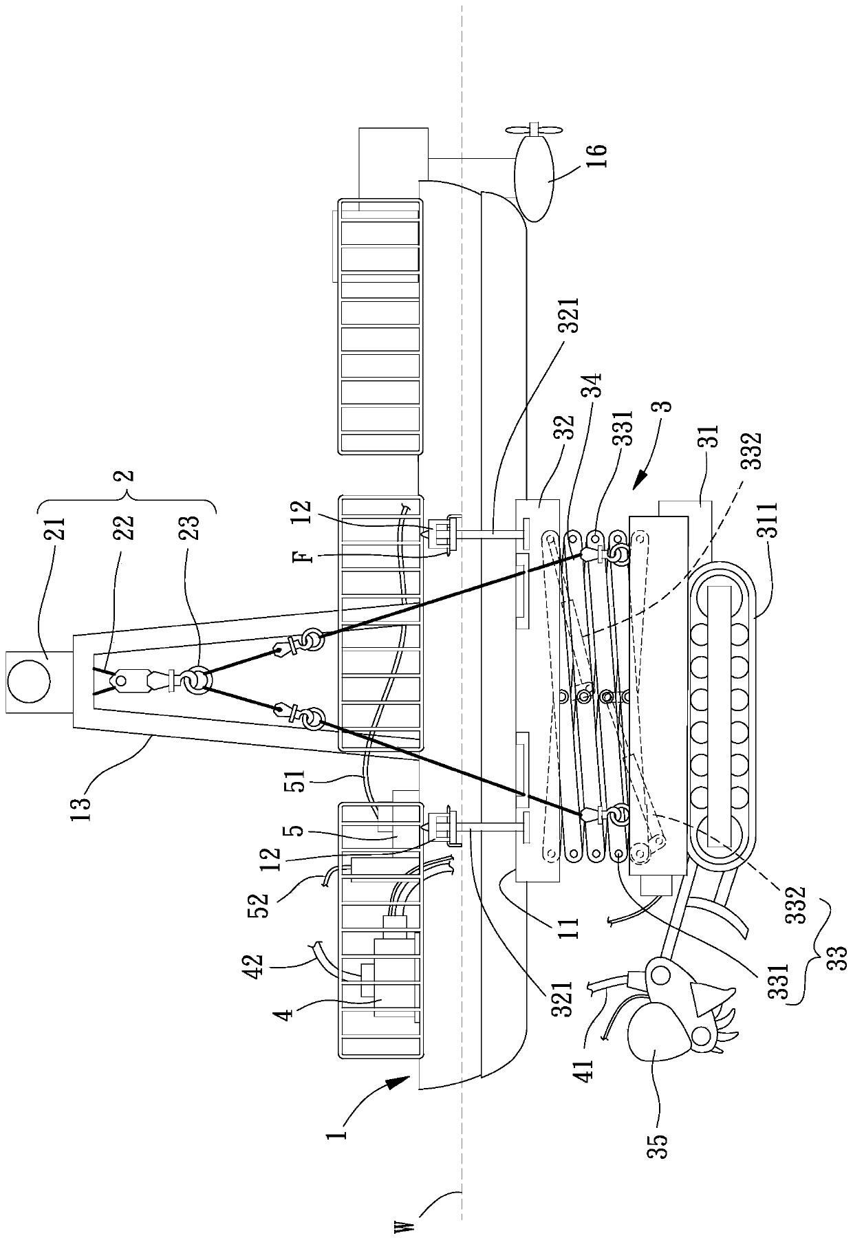
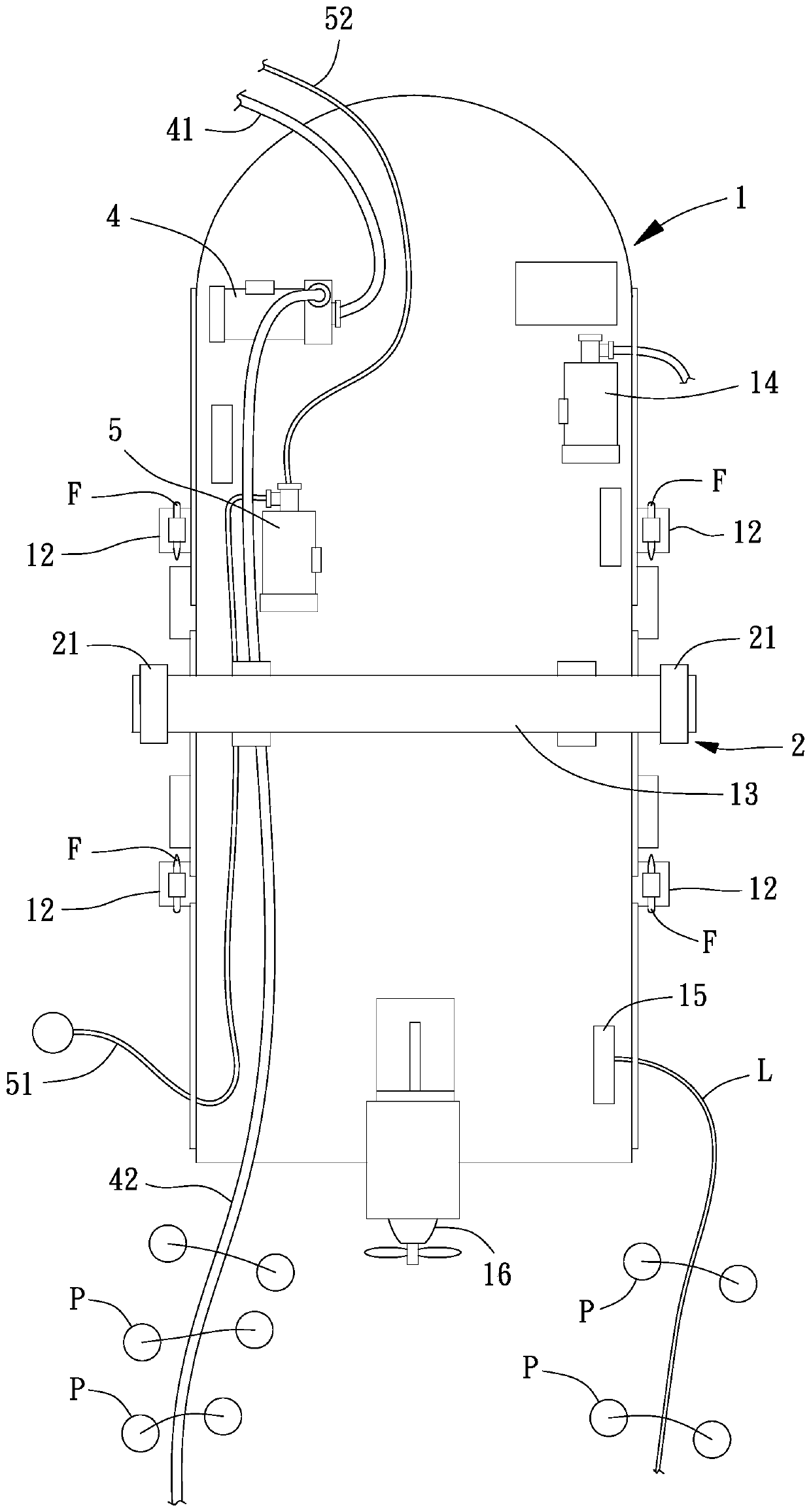
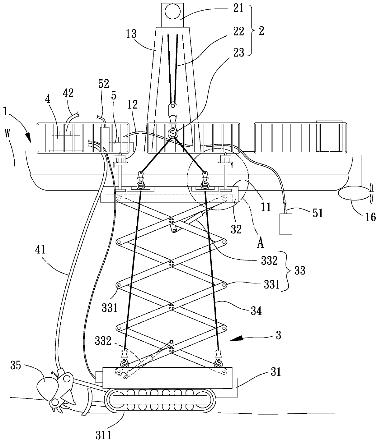
[0025] Please refer to figure 1 As shown, it is the first embodiment of the silt removal device of the present invention, comprising a floating platform 1, a rolling module 2, a self-propelled module 3 and a pumping and transporting mud module 4, and the rolling module 2 is located on the floating platform 1. The self-propelled module 3 is located under the buoy 1 , and the pumping mud module 4 is located on the buoy 1 and connected to the self-propelled module 3 .

[0026] Please refer to figure 1 , Figure 4 As shown, the floating platform 1 can be a kind of hull structure, and the floating platform 1 can float on a water body W, for example: pools, reservoirs, rivers, oceans or la...


PUM


Abstract

The invention provides a sludge removing device which is used for solving the problem that existing sludge removing operation is poor in convenience. The sludge removing device comprises a floating platform, a rolling and hanging module positioned on the floating platform, a self-walking module located below the floating platform, and a sludge pumping and conveying module; the self-walking moduleand the floating platform can be separated or combined, the self-walking module is provided with a walking base and a plate, the plate is connected with the floating platform and the rolling and hanging module, the walking base can axially move relative to the plate, the self-walking module is provided with a reamer sludge cutting piece, and the reamer sludge cutting piece is connected with the walking base; the sludge pumping and conveying module is positioned on the floating platform and provided with a sludge pumping pipe, and the sludge pumping pipe is connected with the reamer sludge cutting piece.

Description

technical field [0001] The invention relates to a clearing device, in particular to a sludge clearing device for clearing underwater sludge. Background technique [0002] Although the reservoir can store water, it also accumulates the sediment washed down from the upstream. Over time, the life of the reservoir is shortened and the water storage capacity is greatly reduced. Therefore, dredging operations must be carried out to prolong the life of the reservoir. The existing silt removal device has a floating table and a reamer mud-cutting suction head, the floating table floats on a water body and is positioned at a predetermined position by using multiple groups of anchors, and the reamer mud-cutting suction head is located on the floating table and agitate the bottom mud at the predetermined position into muddy water, a suction dredging pump is connected to the reamer cutting mud suction head and sucks the muddy water near the predetermined position, and a mud delivery pipe...

Claims


Application Information

Patent Timeline
Patent Type & Authority Applications(China)
IPC IPC(8): E02F5/28E02F3/88E02F3/90E02F3/92E02F7/10
CPCE02F3/88E02F3/885E02F3/8866E02F3/90E02F3/902E02F3/905E02F3/92E02F3/9256E02F3/9281E02F5/28E02F5/282E02F7/10
Inventor 柯世苑
Owner 柯世苑
Why Eureka
Try Eureka