Grading ring with insulating structure

A technology of insulating structure and voltage equalizing ring, applied in the field of equalizing rings, can solve the problems of time-consuming and laborious replacement of equalizing rings, poor insulation at the connection of equalizing rings, and complicated installation of equalizing rings, etc., so as to facilitate maintenance and replacement and reduce emergency repairs. Difficulty, the effect of improving insulation performance

Inactive Publication Date: 2020-04-24
江苏茂斯特电力科技有限公司
0 Cites 1 Cited by

AI-Extracted Technical Summary

Problems solved by technology

[0004] The purpose of the present invention is to provide a voltage equalizing ring with an insulating structure to solve the problems of cumbersome installation of the voltage equ...

Abstract

The invention discloses a grading ring with an insulating structure. The grading ring comprises a tip. A first connecting block is fixedly mounted on the left side of the tip. The left side of the first connecting block is connected with the right side of a second connecting block. A first grading ring is mounted on the left side of the second connecting block, and an insulating device is fixed atthe bottom end of the back surface of the first grading ring. An inclined connecting rod is fixedly mounted at the bottom end of the insulating device. The bottom end of the inclined connecting rod is connected with a second grading ring. A connecting column is fixed on the right side of the back surface of the second grading ring. The right side of the connecting column is fixedly connected witha sleeving device. According to the invention, the sleeving device is arranged, so that the grading ring can be mounted in one step; when the grading ring is aged or damaged and needs to be replaced,only the first grading ring needs to be detached and replaced through the insulating device without screwing; maintenance and replacement are convenient; and the insulating performance of the joint between the ring bodies is remarkably improved through the insulating structure of a hollow insulating block and a pouring sealant.

Application Domain

Technology Topic

Image

  • Grading ring with insulating structure
  • Grading ring with insulating structure
  • Grading ring with insulating structure

Examples

  • Experimental program(1)

Example Embodiment

[0021] The technical solutions in the embodiments of the present invention will be clearly and completely described below in conjunction with the accompanying drawings in the embodiments of the present invention. Obviously, the described embodiments are only a part of the embodiments of the present invention, rather than all the embodiments. Based on the embodiments of the present invention, all other embodiments obtained by those of ordinary skill in the art without creative work shall fall within the protection scope of the present invention.
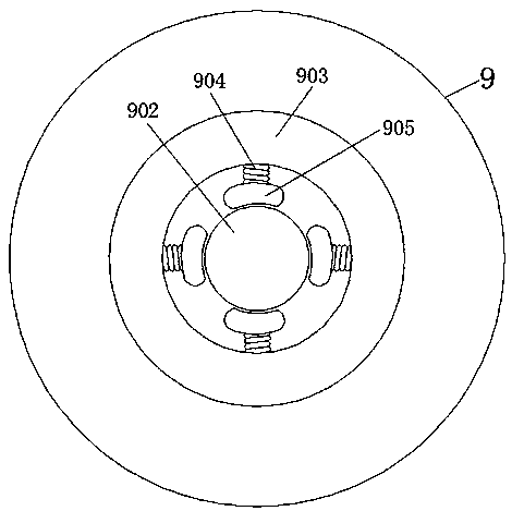
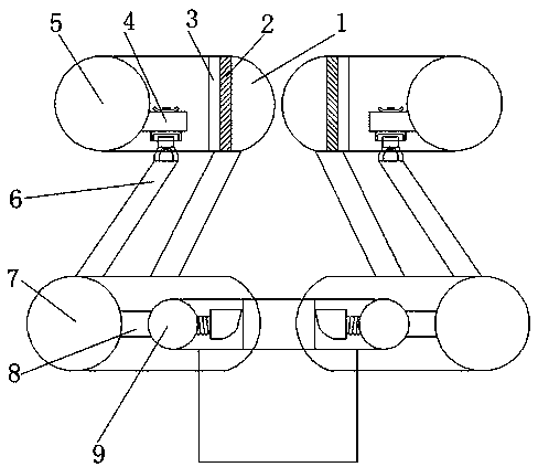
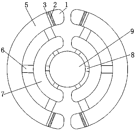
[0022] See Figure 1-5 , An embodiment provided by the present invention: a pressure equalizing ring with an insulating structure, including a terminal 1, a first connecting block 2 is fixedly installed on the left side of the terminal 1, and the left side of the first connecting block 2 is connected to the The right side of the second connecting block 3 is connected, the left side of the second connecting block 3 is equipped with a first equalizing ring 5, and the bottom end of the back of the first equalizing ring 5 is fixed with an insulating device 4, preferably an insulating device 4 Including a screw 401, a fixing piece 402, a first connecting rod 403, a hollow insulating block 404, a potting glue 405, and a docking block 406. The bottom end of the screw 401 is provided with a fixing piece 402, and the bottom end of the fixing piece 402 is connected with a second A connecting rod 403, the bottom end of the first connecting rod 403 is installed with a hollow insulating block 404, and the inner bottom end of the hollow insulating block 404 is connected with a potting glue 405. The hollow insulating block 404 and the potting glue 405 are made of ring It is made of oxygen resin, modified curing agent, silicon dioxide, fiber and other materials. The bottom end of the potting glue 405 is equipped with a butting block 406, which is placed through the insulating device 4. When the equalizing ring is aging or damaged and needs to be replaced, only The first equalizing ring 5 needs to be removed and replaced, and the entire string of insulators installed inside the first equalizing ring 5 can be replaced after removal, which is convenient for maintenance and replacement, greatly reduces the difficulty of repairing and reduces the workload.
[0023] The bottom end of the insulating device 4 is fixedly installed with an inclined connecting rod 6, and the bottom end of the inclined connecting rod 6 is connected with a second equalizing ring 7, and a connecting post 8 is fixed on the right side of the back of the second equalizing ring 7, and the connecting post A socket device 9 is fixedly connected to the right side of 8. Preferably, the socket device 9 includes a sleeve head 901, a socket rod 902, a socket ring 903, a spring 904, a stop 905 and a second connecting rod 906, and a sleeve The bottom end of the head 901 is welded with a socket rod 902, and the surface of the socket rod 902 is socketed with a socket ring 903. Preferably, both sides of the top end of the socket head 901 are arc-shaped structures, and the stop 905 is close to the second connection The inner side of the bottom end of the rod 906 is an arc-shaped structure. The arc direction on both sides of the top end of the sleeve head 901 is opposite to the inner side of the bottom end of the stop 905. The inner side of the sleeve ring 903 is connected with a spring 904, and the spring 904 is close to the sleeve. A stop 905 is fixedly installed on one side of the rod 902.
[0024] Preferably, there are four sets of stoppers 905, and the stoppers 905 are symmetrically distributed with respect to the central axis of the socket rod 902. The length between each set of stoppers 905 and the inner side of another symmetrical set of stoppers 905 is the same The two ends of the cross section of 902 have the same length, and the bottom end of the socket rod 902 is fixed with a second connecting rod 906. Preferably, the height of the socket rod 902 is the same as the height of the cross-sectional area of ​​the socket ring 903, and the socket ring 903 The diameter of the cross section of the inner ring is the same as the diameter of the cross section of the sleeve head 901. The sleeve connecting device 9 directly presses the sleeve ring 903 on the second connecting rod 906, which can complete the installation of the equalizing ring in one step without the need to install it. Screws, there is no need for people to hold the equalizing ring during installation, which realizes the fast, efficient, and labor-saving installation of the equalizing ring, which improves the universality of the equalizing ring. At the same time, the spring 904 buffers the equalizing ring when the equalizing ring is affected by strong wind. Shaking is not easy to occur, and the use effect of the equalizing ring is improved.
[0025] Working principle: When using, according to Figure 4 , The first equalizing ring 5 and the second equalizing ring 7 move down at the same time, the second equalizing ring 7 drives the sleeve ring 903 to move down through the connecting column 8, and the stopper 905 moves to the top of the sleeve head 901 , The arc on the inner side of the bottom end of the stopper 905 passes through the arc at the top of the sleeve head 901, the stopper 905 moves downward to press the spring 904 to one side of the sleeve ring 903, and the stopper 905 moves to the bottom of the sleeve head 901 When the end, the stopper 905 moves to one side of the socket rod 902 under the action of the spring 904, the stopper 905 clamps the sleeve head 901, the position of the socket ring 903 is fixed, and the socket ring 903 is sleeved in the second connection On the rod 906, the installation of the equalizing ring can be completed in one step, without screws, which realizes the fast, efficient and labor-saving installation of the first equalizing ring 5 and the second equalizing ring 7. At the same time, the first equalizing ring is buffered by the spring 904. The ring 5 and the second equalizing ring 7 are not prone to shaking when affected by strong wind, which improves the use effect of the equalizing ring.
[0026] When the equalizing ring is aging or damaged and needs to be replaced, according to image 3 , Remove the screw 401. After the screw 401 is removed, the first connecting rod 403 is separated from the fixing piece 402 and the hollow insulating block 404. The first connecting rod 403 and the first equalizing ring 5 can be directly removed and replaced without the first equalizing The entire string of insulators installed inside the pressure ring 5 can be replaced after removal, which greatly reduces the difficulty of repair and reduces the workload. At the same time, the insulating structure of the hollow insulation block 404 and the potting compound 405, the hollow insulation block 404 and the potting compound 405 The combined use of, the insulation performance of the joint between the ring bodies is significantly improved, and the physical safety of maintenance personnel is improved.
[0027] For those skilled in the art, it is obvious that the present invention is not limited to the details of the foregoing exemplary embodiments, and the present invention can be implemented in other specific forms without departing from the spirit or basic characteristics of the present invention. Therefore, from any point of view, the embodiments should be regarded as exemplary and non-limiting. The scope of the present invention is defined by the appended claims rather than the foregoing description, and therefore it is intended to fall within the claims. All changes within the meaning and scope of equivalent elements of are included in the present invention. Any reference signs in the claims should not be regarded as limiting the claims involved.

PUM

no PUM

Description & Claims & Application Information

We can also present the details of the Description, Claims and Application information to help users get a comprehensive understanding of the technical details of the patent, such as background art, summary of invention, brief description of drawings, description of embodiments, and other original content. On the other hand, users can also determine the specific scope of protection of the technology through the list of claims; as well as understand the changes in the life cycle of the technology with the presentation of the patent timeline. Login to view more.

Similar technology patents

Biconical high consistency refiner

InactiveCN103924472ASimplify design and installationEasy to repair and replacePulp beating/refining methodsStatorAxial length
Owner:TIANJIN UNIVERSITY OF SCIENCE AND TECHNOLOGY

Classification and recommendation of technical efficacy words

  • Easy to repair and replace
  • Improve insulation performance

Non-inflation low-speed cross-country vehicle tire

PendingCN106915203AEasy to repair and replaceAvoid damageNon-inflatable tyresOff-road vehicle tyresAir springLow speed
Owner:SHANDONG JIANZHU UNIV +1

Method for preparing transformer insulating heat conduction oil

InactiveCN105779094AImprove insulation performanceBlock direct contactAdditivesCorrosionGlycerol
Owner:SUZHOU SICHUANGYUANBO ELECTRONICS TECH CO LTD
Why Eureka
Try Eureka