
Protection circuit and variable pitch system

A technology for protection circuits and overcurrent protection circuits, applied in emergency protection circuit devices, circuit devices, emergency protection circuit devices for limiting overcurrent/overvoltage, etc., can solve key component damage, high residual voltage of power supply, easy Affected by surge interference and other problems, to achieve the effect of improving reliability, good protection, and improving reliability

Pending Publication Date: 2020-04-24
BEIJING ETECHWIN ELECTRIC
View PDF0 Cites 2 Cited by
  • Summary
  • Abstract
  • Description
  • Claims
  • Application Information

AI Technical Summary

Problems solved by technology

[0004] Wind turbines are usually built in sparsely populated places with harsh environments, especially affected by lightning weather, and are susceptible to surge interference during work. Frequently, weak current systems have problems with weak current power supply systems due to direct lightning strikes, induction lightning, switching surges, etc.
[0005] The inventor of the present application has researched the prior art and found that in the prior art, in order to improve the reliability of the power supply, the usual method is to install an anti-lightning surge protection module at the input end of the PLC power supply. Although the anti-lightning surge protection module It can solve some problems, but there is a problem of high residual voltage of the output power supply, which will cause a lot of damage to key components such as PLC during the thunderstorm season, and the lightning protection surge protection module has a short service life, which needs to be checked and replaced regularly

Method used


Image

  • Protection circuit and variable pitch system
  • Protection circuit and variable pitch system
  • Protection circuit and variable pitch system

Examples


Embodiment Construction

[0069] Embodiments of the present application are described in detail below, examples of which are shown in the drawings, wherein the same or similar reference numerals denote the same or similar elements or elements having the same or similar functions throughout. The embodiments described below by referring to the figures are exemplary only for explaining the present application, and are not construed as limiting the present application.

[0070] Those skilled in the art will understand that unless otherwise stated, the singular forms "a", "an", "said" and "the" used herein may also include plural forms. It should be further understood that the word "comprising" used in the specification of the present application refers to the presence of the features, integers, steps, operations, elements and / or components, but does not exclude the presence or addition of one or more other features, Integers, steps, operations, elements, components, and / or combinations thereof. It will be...


PUM


Abstract

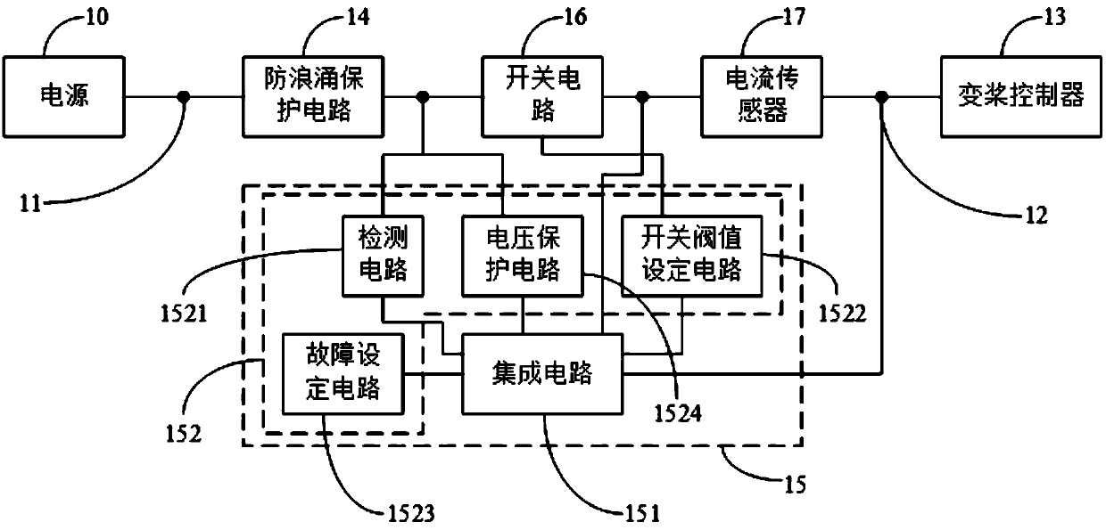
The embodiment of the invention provides a protection circuit and a variable pitch system, which are applied to a wind generating set. An input interface of the protection circuit is connected with apower supply of a variable pitch controller, and an output interface of the protection circuit is connected with the variable pitch controller. The protection circuit comprises an anti-surge protection circuit, a main protection circuit, a switching circuit and a current sensor which are connected between the input interface and the output interface. The main protection circuit is used for clamping the voltage of the control end of the switching circuit when detecting that surge occurs to the input voltage of the switching circuit, so that the output voltage of the switching circuit is limitedwithin a specified voltage range. When instantaneous overcurrent of the output current of the switching circuit is detected through the current sensor, the output current of the switching circuit islimited, or the switching circuit is controlled to be in a closed state. When the fact that the input voltage of the switching circuit is continuously overvoltage and / or the input current of the switching circuit is continuously overcurrent in a set time period is detected, the switching circuit is controlled to be in an off state.

Description

technical field [0001] The present application relates to the technical field of wind power generation, and in particular, the present application relates to a protection circuit and a pitch control system. Background technique [0002] The control core of the wind turbine pitch system is PLC (Programmable Logic Controller, Programmable Logic Controller). If there is a problem with the weak current system, the PLC will not work properly. [0003] The power supply for PLC is generally +24 volt power supply. When working, the reliability requirements of this power supply are relatively high, far exceeding the power supply requirements of the general industrial control field. An important factor affecting reliability is its anti-interference and anti-lightning surge ability. [0004] Wind turbines are usually built in sparsely populated places with harsh environments, especially affected by lightning weather, and are susceptible to surge interference during work. Frequently, ...

Claims


Application Information

Patent Timeline
Patent Type & Authority Applications(China)
IPC IPC(8): H02H9/04H02H9/02H02H3/02
CPCH02H3/025H02H9/02H02H9/04
Inventor 张智勇
Owner BEIJING ETECHWIN ELECTRIC
Learn More