Voltage and capacitance regulation compensation device

A technology of compensation device and voltage regulator, which is applied in the field of capacitor compensation, can solve the problems of affecting the operating life of capacitors, the inability to realize fine adjustment, and affecting the life of capacitors, so as to achieve the effects of prolonging life, reducing impact, and reducing line loss

Inactive Publication Date: 2018-04-06
无锡市锡容电力电器有限公司
View PDF3 Cites 0 Cited by
  • Summary
  • Abstract
  • Description
  • Claims
  • Application Information

AI Technical Summary

Problems solved by technology

The problems existing in the traditional adjustable capacitor bank are as follows: 1. No matter how the capacitors are grouped, it is impossible to fully adapt to the change of system inductive reactive power. It can only be adjusted within a large range and cannot be fine-tuned; 2. Capacitor switching Overvoltage is generated, so frequent operation will seriously affect the life of the capacitor; 3. The inrush current problem of the capacitor during operation is generally limited by a series reactor, which inevitably sacrifices a part of the capacitor capacity to offset the loss of the reactor, and the series reactor It also increases the operating voltage of the capacitor, seriously affecting the operating life of the capacitor

Method used


Image

  • Voltage and capacitance regulation compensation device

Examples


Embodiment Construction

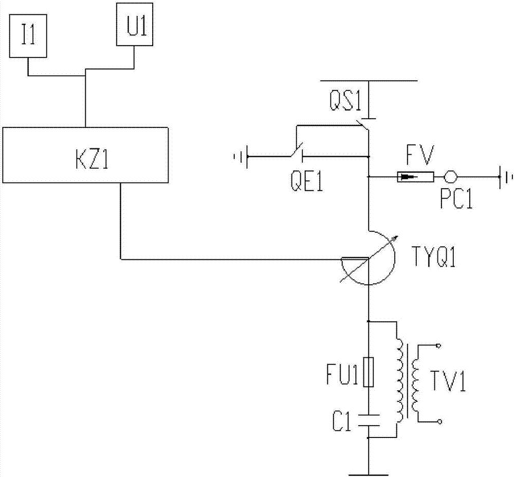
[0011] In order to facilitate the understanding of the present invention, the present invention will be described more fully below with reference to the associated drawings. Preferred embodiments of the invention are shown in the accompanying drawings. However, the present invention can be embodied in many different forms and is not limited to the embodiments described herein. On the contrary, the purpose of providing these embodiments is to make the disclosure of the present invention more thorough and comprehensive. It should be noted that when an element is considered to be "connected" to another element, it may be directly connected to the other element or there may be intervening elements at the same time. Unless otherwise defined, all technical and scientific terms used herein have the same meaning as commonly understood by one of ordinary skill in the technical field of the invention. The terms used herein in the description of the present invention are for the purpos...


PUM


Abstract

The invention discloses a voltage and capacitance regulation compensation device comprising a capacitor C1, a fuse FU1, a voltage regulator TYQ1, a transformer TV1, a discharge counter PC1, a lightning arrester FV1, a controller KZ1, an isolation switch QS1 and a grounding switch QE1. One end of the capacitor C1 is connected to one end of a primary coil, and the other end is connected to one end of the fuse FU1. The other end of the fuse FU1 is connected to the other end of the primary coil and a first wiring terminal of the voltage regulator TYQ1. A second wiring end of the voltage regulatorTYQ1 is connected to the controller KZ1. One end of the lightning arrester FV1 is connected to one end of an isolation switch QS1 and one end of the grounding switch QE1, and the other end of the grounding switch QE1 is grounded. One end of the discharge counter PC1 is connected to the other end of the lightning arrester FV1, and the other end of discharge counter PC1 is grounded. The problems ofover-voltage and inrush current in capacitor switching are solved.

Description

technical field [0001] The invention relates to the technical field of capacitor compensation, in particular to a compensation device for voltage regulation and capacity regulation. Background technique [0002] Due to the expansion of grid capacity and the increase of voltage levels, it is of great significance to maintain the normal voltage of grids at all levels and each user, so as to ensure the safe and economical operation of the grid and the normal use of electricity by users, which is of great significance to the development of the national economy. The optimal switching of capacitors in the distribution network is used to determine the switching strategy of the installed capacitor banks in the distribution system under different load conditions. For the adjustable capacitor banks, it is also necessary to determine the switching array. The problems existing in the traditional adjustable capacitor bank are as follows: 1. No matter how the capacitors are grouped, it is...

Claims


Application Information

Patent Timeline
Patent Type & Authority Applications(China)
IPC IPC(8): H02J3/18
CPCY02E40/30H02J3/18
Inventor 谷霄飞
Owner 无锡市锡容电力电器有限公司
Why Eureka
Try Eureka