Low-cost battery charging circuit

A battery charging, low-cost technology, applied to battery circuit devices, circuit devices, collectors, etc., can solve problems such as affecting life, high cost, and battery damage, and achieve the effect of charging management

Pending Publication Date: 2020-04-24
深圳市锐同技术有限公司
View PDF0 Cites 0 Cited by
  • Summary
  • Abstract
  • Description
  • Claims
  • Application Information

AI Technical Summary

Problems solved by technology

The cost of the former is too high, and the latter is too harmful to the battery and affects its life

Method used


Image

  • Low-cost battery charging circuit

Examples


Embodiment Construction

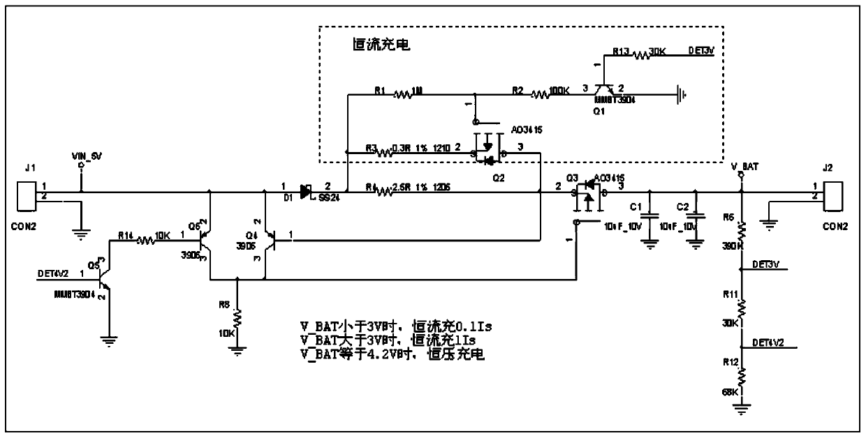
[0012] The specific embodiments of the present invention will be further described below in conjunction with the accompanying drawings. It should be noted here that the descriptions of these embodiments are used to help understand the present invention, but are not intended to limit the present invention. In addition, the technical features involved in the embodiments of the present invention described below may be combined with each other as long as they do not conflict with each other.

[0013] As shown in the accompanying drawings: a low-cost battery charging circuit, including a power input terminal J1, a power output terminal J2, a diode D1, a transistor Q1, a MOS transistor Q2, a MOS transistor Q3, a transistor Q4, a transistor Q5, and a transistor Q6. The input terminal of the power supply is respectively connected to the anode of the diode D1, the emitters of the transistor Q4 and the transistor Q6, the cathode of the diode D1 is connected to one end of the resistor R4...


PUM


Abstract

The invention relates to the technical field of battery charging circuits, and particularly relates to a low-cost battery charging circuit. The circuit comprises a power supply input end J1 and a power supply output end J2, the power input end is connected with the positive electrode of a diode D1, the emitting electrode of a triode Q4 and the emitting electrode of a triode Q6 respectively, the negative electrode of the diode D1 is connected with one end of a resistor R4 and a constant-current charging circuit, the other end of the resistor R4 is connected with the source electrode of an MOS tube Q3, the drain electrode of the MOS tube Q3 is connected with a capacitor C1, a capacitor C2 and the power supply output end J2, the base electrode of the triode Q4 is connected with the source electrode of the MOS tube Q3, the collector electrode of the triode Q4 is connected with a resistor R8 and the grid electrode of the MOS tube Q3, the collector electrode of the triode Q6 is connected with the resistor R8, the base electrode of the triode Q6 is connected with a resistor R14, and the other end of the resistor R14 is connected with the collector electrode of a triode Q5. The circuit adopts a small number of triodes, MOS tubes, resistors and capacitors to realize battery charging management.

Description

technical field [0001] The invention relates to the technical field of battery charging circuits, in particular to a low-cost battery charging circuit. Background technique [0002] There are usually two methods for portable electronic products with battery charging function, one is to use an expensive charge management chip, and the other is to charge the battery directly with a current limiting resistor. The cost of the former is too high, and the latter damages the battery too much and affects its life. Contents of the invention [0003] In order to overcome the above-mentioned defects of the prior art, the present invention provides a low-cost battery charging circuit to solve the problems raised in the above-mentioned background art. [0004] The technical solution adopted by the present invention to solve the problems in the prior art is: a low-cost battery charging circuit, including a power input terminal J1, a power output terminal J2, a diode D1, a transistor Q1...

Claims


Application Information

Patent Timeline
Patent Type & Authority Applications(China)
IPC IPC(8): H02J7/00
Inventor 骆小煌吴灿阳
Owner 深圳市锐同技术有限公司
Why Eureka
Try Eureka