Rotary compressor

A rotary compressor and rotary shaft technology, applied in the field of compressors, can solve the problems of increasing the mechanical friction loss, increasing the friction area between the blades and the cylinder, and achieve the effect of suppressing the increase of the mechanical friction loss

Active Publication Date: 2020-04-24
LG ELECTRONICS INC
View PDF9 Cites 0 Cited by
  • Summary
  • Abstract
  • Description
  • Claims
  • Application Information

AI Technical Summary

Problems solved by technology

However, if the number of blades is increased or the volume (or number) of the cylinder is increased, the friction area between the blades and the cylinder will be increased accordingly, and the mechanical friction loss will be further increased

Method used


Image

  • Rotary compressor
  • Rotary compressor
  • Rotary compressor

Examples


Embodiment Construction

[0059] Hereinafter, a rotary compressor related to the present invention will be described in detail with reference to the drawings.

[0060] In this specification, expressions in the singular shall include expressions in the plural unless the context clearly indicates otherwise.

[0061] In the process of describing the embodiments disclosed in this specification, if it is judged that the specific description of related known technologies will make the gist of the embodiments disclosed in this specification unclear, the detailed description will be omitted.

[0062] The accompanying drawings are only to help understand the embodiments disclosed in this specification, and the technical ideas disclosed in this specification are not limited by the accompanying drawings. It should be understood that the present invention includes the ideas of the present invention and all changes, equivalents and substitutes within the technical scope.

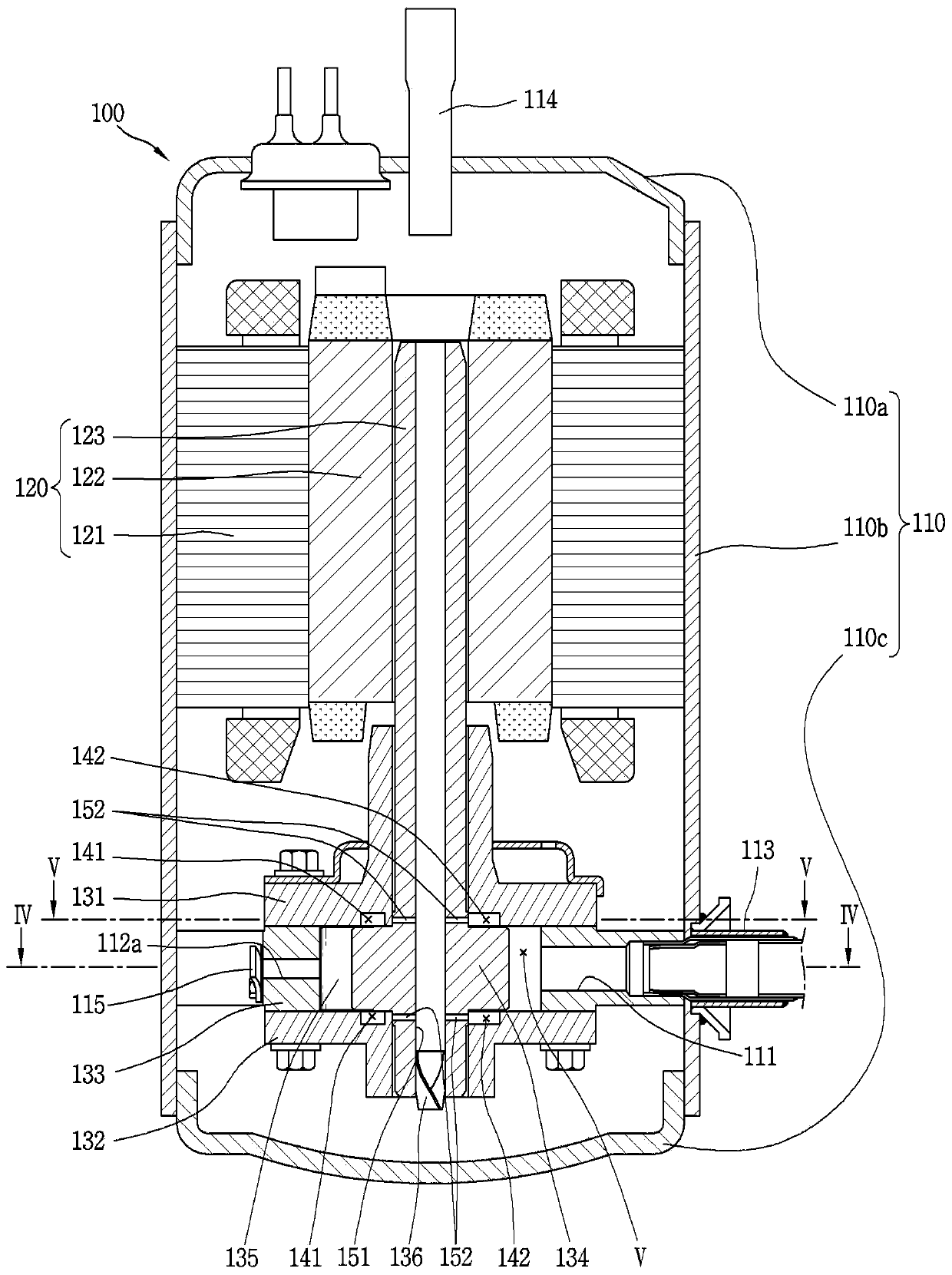
[0063] image 3 It is a sectional view sh...


PUM


Abstract

The present invention relates to a rotary compressor comprising: a drive motor; a rotational shaft; a main bearing and a sub-bearing fixed to a case and installed along the rotational shaft; a cylinder; a roller; and at least two vanes, wherein back pressure spaces are respectively formed along a predetermined radius on the bottom surface of the main bearing or the top surface of the sub-bearing,and oil flowing along an oil flow channel is received in each of the back pressure spaces so as to enable pressure to be transferred to the respective rear end portions of the vanes.

Description

technical field [0001] The present invention relates to a compressor, in particular to a rotary compressor (Rotary Compressor) provided with blades. Background technique [0002] Generally, compressors can be classified into rotary and reciprocating according to the way of compressing refrigerant. A rotary compressor is a method in which the piston changes the volume of the compression space when the cylinder rotates or revolves, and a reciprocating compressor is a method in which the piston changes the volume of the compression space when the cylinder reciprocates. As a rotary compressor, there is known a rotary compressor that uses a rotational force of an electric unit to rotate a piston and compress refrigerant. [0003] Rotary compressors continue to develop technologies related to efficiency and miniaturization. In addition, a technology that satisfies more cooling capacity (Cooling Capacity) by increasing the variable range of the operating speed of the compressor i...

Claims


Application Information

Patent Timeline
Patent Type & Authority Applications(China)
IPC IPC(8): F04C18/344F04C29/02F04C29/06F04C28/22
CPCF04C28/22F04C29/02F04C29/06F04C18/344
Inventor 辛镇雄文石焕李丙哲
Owner LG ELECTRONICS INC
Why Eureka
Try Eureka