Rotary compressor

A rotary compressor and rotary shaft technology, applied in the field of compressors, can solve the problems of increasing the friction area between blades and cylinders, increasing mechanical friction loss, etc., and achieve the effects of reducing mechanical friction loss, reducing pressure pulsation, and stabilizing the contact state

Active Publication Date: 2022-07-26
LG ELECTRONICS INC
View PDF9 Cites 0 Cited by
  • Summary
  • Abstract
  • Description
  • Claims
  • Application Information

AI Technical Summary

Problems solved by technology

However, if the number of blades is increased or the volume (or number) of the cylinder is increased, the friction area between the blades and the cylinder will be increased accordingly, and the mechanical friction loss will be further increased

Method used


Image

  • Rotary compressor
  • Rotary compressor
  • Rotary compressor

Examples


Embodiment Construction

[0059] Hereinafter, the rotary compressor according to the present invention will be described in detail with reference to the accompanying drawings.

[0060] In this specification, expressions in the singular shall include expressions in the plural unless the context clearly indicates otherwise.

[0061] During the description of the embodiments disclosed in this specification, if it is determined that the specific description of the related well-known technology makes the gist of the embodiments disclosed in this specification unclear, the detailed description thereof will be omitted.

[0062] The accompanying drawings are only to help understand the embodiments disclosed in this specification, the technical ideas disclosed in this specification are not limited by the accompanying drawings, and it should be understood that the present invention includes all changes, equivalents and substitutes within the technical scope of the present invention.

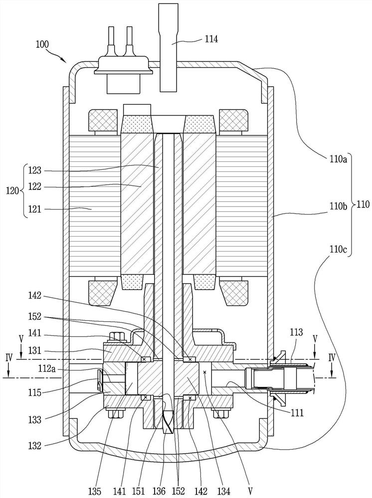
[0063] image 3 It is sect...


PUM


Abstract

The present invention relates to a rotary compressor comprising: a driving motor; a rotating shaft; a main bearing and an auxiliary bearing fixed to the casing and arranged along the rotating shaft; a cylinder; a roller; and two or more A back pressure space is formed on the bottom surface of the main bearing or the top surface of the sub bearing along a predetermined radius, respectively, and the oil moving along the oil flow path is accommodated in each of the back pressure spaces, and thereby Pressure is transmitted to the rear end of each of the vanes.

Description

technical field [0001] The present invention relates to a compressor, and more particularly, to a rotary compressor (Rotary Compressor) provided with blades. Background technique [0002] Generally, compressors can be classified into rotary type and reciprocating type according to the way of compressing refrigerant. A rotary compressor is a method in which the piston changes the volume of the compression space when the cylinder rotates or swivels, and a reciprocating compressor is a method in which the piston changes the volume of the compression space when the cylinder reciprocates. As a rotary compressor, there is known a rotary compressor that compresses a refrigerant by rotating a piston using the rotational force of an electric part. [0003] Rotary compressors continue to develop technologies related to high efficiency and miniaturization. In addition, a technology is currently being developed to satisfy more cooling capacity (Cooling Capacity) by increasing the vari...

Claims


Application Information

Patent Timeline
Patent Type & Authority Patents(China)
IPC IPC(8): F04C18/344F04C29/02F04C29/06F04C28/22
CPCF04C28/22F04C29/02F04C29/06F04C18/344
Inventor 辛镇雄文石焕李丙哲
Owner LG ELECTRONICS INC
Why Eureka
Try Eureka