
Fluidized bed reactor and application method thereof, and hydrocarbon oil desulfurization method

A fluidized bed reactor and reactor technology, applied in the field of fluidized bed reactor and gasoline adsorption desulfurization, can solve the problems affecting the stable operation of the device and the inability to discharge the reactor, so as to achieve good reaction effect, reduce crushing effect, avoid cumulative effect

Active Publication Date: 2020-04-28
CHINA PETROLEUM & CHEM CORP +1
View PDF6 Cites 2 Cited by
  • Summary
  • Abstract
  • Description
  • Claims
  • Application Information

AI Technical Summary

Problems solved by technology

However, in the fluidized adsorption reactor, the fine powder of the catalyst and the fine powder produced by the long-term wear of the particles will be elucidated into the sedimentation space of the fluidized bed for long-term suspension, so that the suspended particles have no chance to return to the dense bed of the fluidized bed , and cannot be discharged from the reactor, which will affect the stable operation of the device in the long run

Method used


Image

  • Fluidized bed reactor and application method thereof, and hydrocarbon oil desulfurization method
  • Fluidized bed reactor and application method thereof, and hydrocarbon oil desulfurization method
  • Fluidized bed reactor and application method thereof, and hydrocarbon oil desulfurization method

Examples


specific Embodiment approach

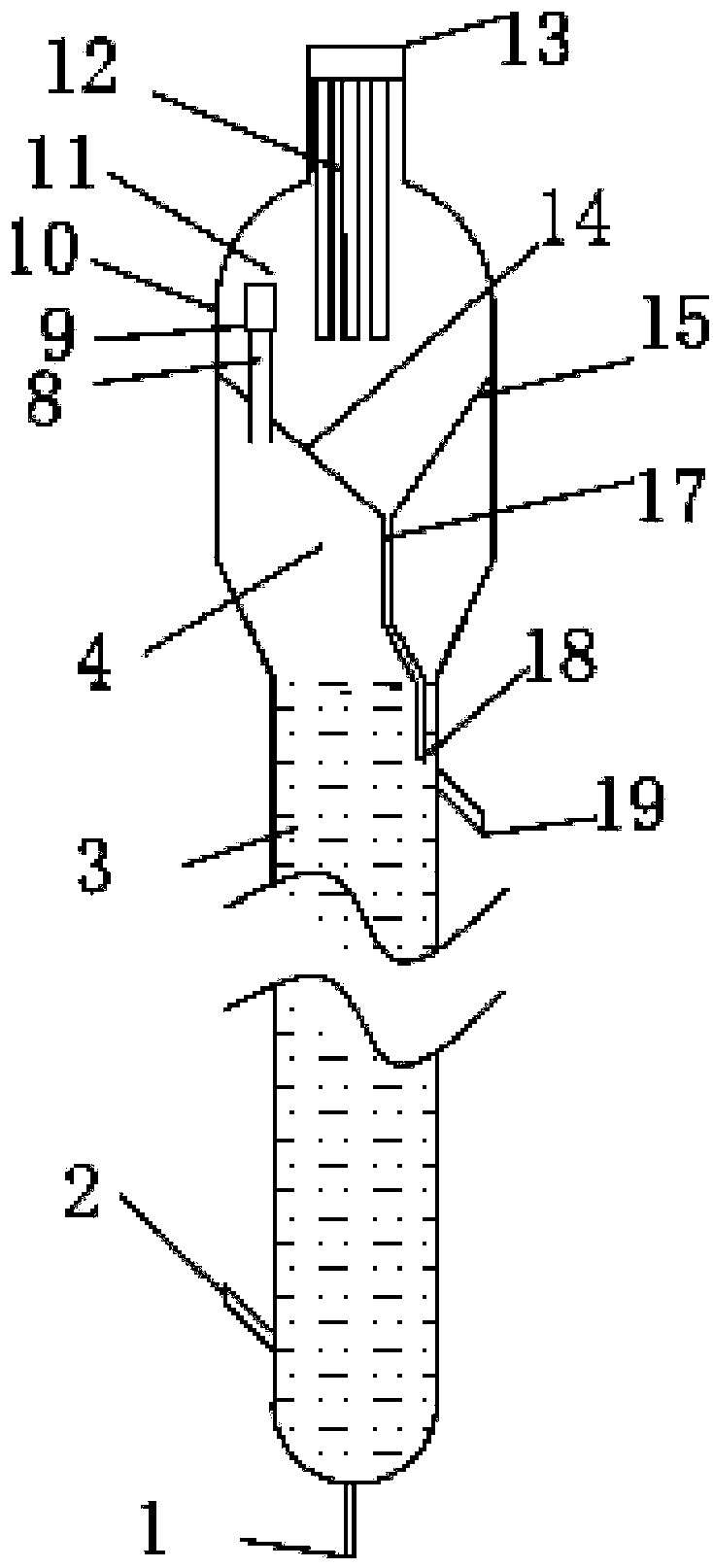
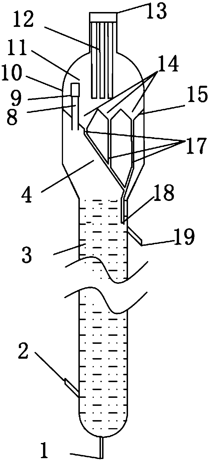
[0068] attached figure 1 A structural schematic diagram of an embodiment of the fluidized bed reactor provided by the present invention, as attached figure 1 As shown, the internal space of the fluidized bed reactor body includes the reaction section 3 and the settling section from bottom to top. The settling section is provided with a partition member 14 to divide the settling section into an upper space 11 of the settling section and a lower space 4 of the settling section, wherein the upper space of the settling section is provided with a filter 12 and a fluid guiding structure 9 . The filter 12 communicates with the gas outlet 13 . The fluid guiding structure 9 is provided with a delivery pipe 8 passing through the baffle plate 15 to change the flow direction of the gas-solid fluid from the lower space 4 of the settling section to enter the upper area 11 of the settling section in a swirling manner.

[0069] The partition member 14 includes a plurality of members that ar...

Embodiment 1

[0088] use as figure 1 The fluidized bed reactor shown has the following structure: a partition member 14 is provided in the settling zone of the reactor, the inclination angle of the baffle plate 15 is 60°, and the opening cross section of the partition member 14 is circular. The upper part of the settling zone is provided with a metal filter tube filter 13, and the lower area 4 of the settling section is not provided with a gas-solid separation device. There are two conveying pipes entering the upper settling space and two fluid guiding outlet structures, which are evenly distributed along the circumference. The nozzle of the conveying pipe 8 protrudes from the partition member 14 at a distance of 200 mm. The aspect ratio of the outlet channel opening of the fluid guide outlet structure 9 is 3:1, and the ratio of the radius of the outer wall of the outlet channel to the radius of the settlement zone is 0.9. The angle a between the outlet normal vector of the arc-shaped pass...

Embodiment 2

[0095] Embodiment 2 adopts the reactor identical with embodiment 1, append figure 1 The fluidized bed reactor shown is different from Example 1 in that the ratio of the outer edge radius R1 of the arc channel to the upper space of the settling section of the reactor is 0.6, and the outlet normal vector of the arc channel and the settling area are at Here, the included angle a of the tangent is 8°, and the ratio of the arc length of the arc channel projected on the horizontal plane to the circumference length is 0.05. The ratio of the cross-sectional area of ​​the delivery pipe 8 to the cross-sectional area of ​​the settlement zone is 0.025. The outlet gas velocity of the fluid guide outlet structure 9 is 6m / s. The exit channel is inclined downward, and the distance between the entrance and exit of the exit channel is 300mm.

[0096] Reaction system and method, sulfur-containing hydrocarbon oil raw material, and reaction conditions are the same as in Example 1.

[0097] The ...


PUM


Abstract

The invention discloses a fluidized bed reactor and an application method thereof, and a hydrocarbon oil desulfurization method. The fluidized bed reactor comprises a reaction section (3) at the lowerportion and a settling section at the upper portion, wherein the settling section is divided into a settling section upper space and a settling section lower space by a separation component (14), theseparation component (14) is composed of a cone-like body and a discharging pipe (17), the cone skirt edge on the top is seamlessly connected with the reactor cylinder, a fluid guide structure (9) isarranged in the settling section upper space, penetrates through the separation component (14) through a conveying pipe (8) and is opened in the settling section upper space, the bottom of the discharging pipe (17) of the separation component (14) is opened in the reaction section (3), and a gas outlet is formed in the top of the settling section upper space through a filter. According to the fluidized bed reactor provided by the invention, separated catalyst fine powder particles can be timely conveyed to the dense-phase bed layer of a reactor, so that the suspension amount of the catalyst particles in the settling zone of the fluidized bed reactor is remarkably reduced, and the operation period of the device is prolonged.

Description

technical field [0001] The invention relates to a fluidized bed reactor in the field of oil refining and chemical industry and an application method thereof, more specifically, to a fluidized bed reactor and a gasoline adsorption desulfurization method using the fluidized bed reactor. Background technique [0002] With the continuous improvement of environmental protection requirements, the indicators of gasoline sulfur content are becoming increasingly stringent. This puts forward higher requirements for gasoline desulfurization technology. The fluidized bed gasoline desulfurization process is an important gasoline desulfurization process. [0003] CN1658965A proposes a method and device for desulfurization from hydrocarbon-containing fluid, wherein the desulfurization is enhanced by improving the contact between hydrocarbon-containing fluid and sulfur-absorbing solid particles in a fluidized bed reactor. The reactor adopts a fluidized bed reactor. From bottom to top, the...

Claims


Application Information

Patent Timeline
Patent Type & Authority Applications(China)
IPC IPC(8): B01J8/24C10G25/09C10G53/08
CPCB01J8/1872B01J8/24C10G25/09C10G53/08C10G2300/1037C10G2300/104C10G2300/1044C10G2300/202C10G2300/70C10G2400/02
Inventor 朱丙田侯栓弟毛俊义朱振兴毛安国张同旺刘凌涛韩颖
Owner CHINA PETROLEUM & CHEM CORP
Learn More