Bracket of centerless grinding machine

A centerless grinding machine and bracket technology, which is applied in the field of brackets for lifting workpieces, can solve the problems of difficulty in improving the machining accuracy of positioning holes, poor realization accuracy, and complex structure.

Pending Publication Date: 2020-04-28
浙江方圆机床制造有限公司
View PDF0 Cites 3 Cited by
  • Summary
  • Abstract
  • Description
  • Claims
  • Application Information

AI Technical Summary

Problems solved by technology

This accuracy is subject to various restrictions, such as the accuracy and fit between the bracket body and the rotary shaft, the precision and fit between the rotary shaft and the jaw hole, and the geometric error between the guide plate mounting surface of the jaw and the hole.
In the original design, the adjustment ring with accumulative precision error was not designed, and the final accuracy was poor
[0007] In the design of the rotary mechanism of the jaw, since the rotary axis of the jaw is determined by the hole of the bracket body, and the bracket body is large in size and complex in structure, it is difficult to improve the machining accuracy of the positioning hole

Method used


Image

  • Bracket of centerless grinding machine
  • Bracket of centerless grinding machine
  • Bracket of centerless grinding machine

Examples


Embodiment

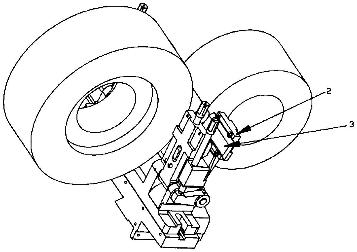
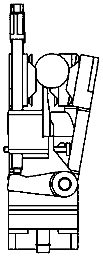
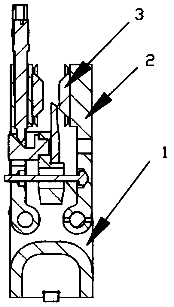
[0026] Such as Figure 4-Figure 11 The shown centerless grinding machine bracket includes a bracket base 1, a jaw 2 movably connected to the bracket base 1, a pallet 13 fixed on the bracket base 1, and a bracket connected to the jaw 2. The guide plate 3, the lower end of the bracket base 1 is connected with a slide plate 4, the jaws 2 described in this embodiment are two groups, and two groups of two are arranged symmetrically, and there are guide plates 3 snapped into each jaw 2. In this embodiment, the groove connects the pressing block 7 at the end of the jaw 2 so that the pressing block 7 extends to the lower end surface of the guide plate 3 and the jaw 2 to form a dovetail groove 5, and the guide plate 3 snaps into the groove. The groove has a gap for adjusting the angle of the guide plate 3, and the jaw 2 is provided with a first adjusting member 6 for adjusting the angle of the guide plate 3, and the guide plate 3 is clamped in the dovetail groove 5 and fixed by the fir...


PUM


Abstract

The invention provides a bracket of a centerless grinding machine. The bracket comprises a bracket seat body, jaws movably connected to the bracket seat body, a supporting plate fixed to the bracket seat body and guide plates connected to the jaws. At least one set of jaws is arranged, and every two jaws form a set. Grooves for the guide plates to be clamped are formed in the inner sides of the jaws. The grooves are directly machined in the inner sides of the jaws or are formed in a combined manner through other parts. After the guide plates are clamped in the grooves, the grooves are providedwith clearances for adjusting the angles of the guide plates. First adjusting parts used for adjusting the angles of the guide plates are arranged on the jaws. By means of the bracket of the centerless grinding machine, the grooves used for clamping connection of the guide plates are designed in the upper portions of the jaws, the guide plates are tightly attached to the planes of the jaws, and the guide plates are locked by guide plate pressing blocks through screws. Meanwhile, the first adjusting parts (guide plate fine adjustment screws) at two positions of the back faces of the jaws can be screwed in and screwed so as to adjust the work planes of the guide plates, and the work planes of the guide plates can be parallel to the working busbar of the bracket. By means of the design, thepositioning rigidity of the guide plates is greatly improved, and the micron order precision can be achieved through adjustment.

Description

technical field [0001] The invention belongs to the technical field of grinding machines, in particular to a bracket for supporting workpieces in a centerless grinding machine. Background technique [0002] When the centerless grinder performs pass-through grinding, the workpiece first passes through the guide area positioned by the bracket guide plate and the supporting plate, and then enters the grinding area where the grinding wheel, the guide wheel and the supporting plate act on the workpiece. In order to achieve higher workpiece precision, the linear motion generatrix of the workpiece determined by the guide plate and the supporting plate in the guide area should coincide with the grinding generatrix of the workpiece determined by the supporting plate and the guide wheel in the grinding area. The superimposed generatrix is ​​usually called Work busbars for the brackets. When the bracket is installed on the grinding machine, the working bus bar of the bracket should al...

Claims


Application Information

Patent Timeline
IPC IPC(8): B24B5/307
CPCB24B5/307
Inventor 杨方刚
Owner 浙江方圆机床制造有限公司
Why Eureka
Try Eureka