Tunnel furnace for terminal cable and use method of tunnel furnace

A technology of cable wire and tunnel furnace, applied in the field of terminal wire processing, can solve the problems of sticking, difficult to cut and so on

Active Publication Date: 2020-04-28
深圳市新都丰电子有限公司
View PDF4 Cites 0 Cited by
  • Summary
  • Abstract
  • Description
  • Claims
  • Application Information

AI Technical Summary

Problems solved by technology

However, due to the high temperature in the drying box, the outer skin of the wire is easy to stick to the conveyor net after being heated, making it difficult to unload

Method used


Image

  • Tunnel furnace for terminal cable and use method of tunnel furnace
  • Tunnel furnace for terminal cable and use method of tunnel furnace
  • Tunnel furnace for terminal cable and use method of tunnel furnace

Examples


Embodiment Construction

[0044] The present invention will be described in further detail below in conjunction with the accompanying drawings.

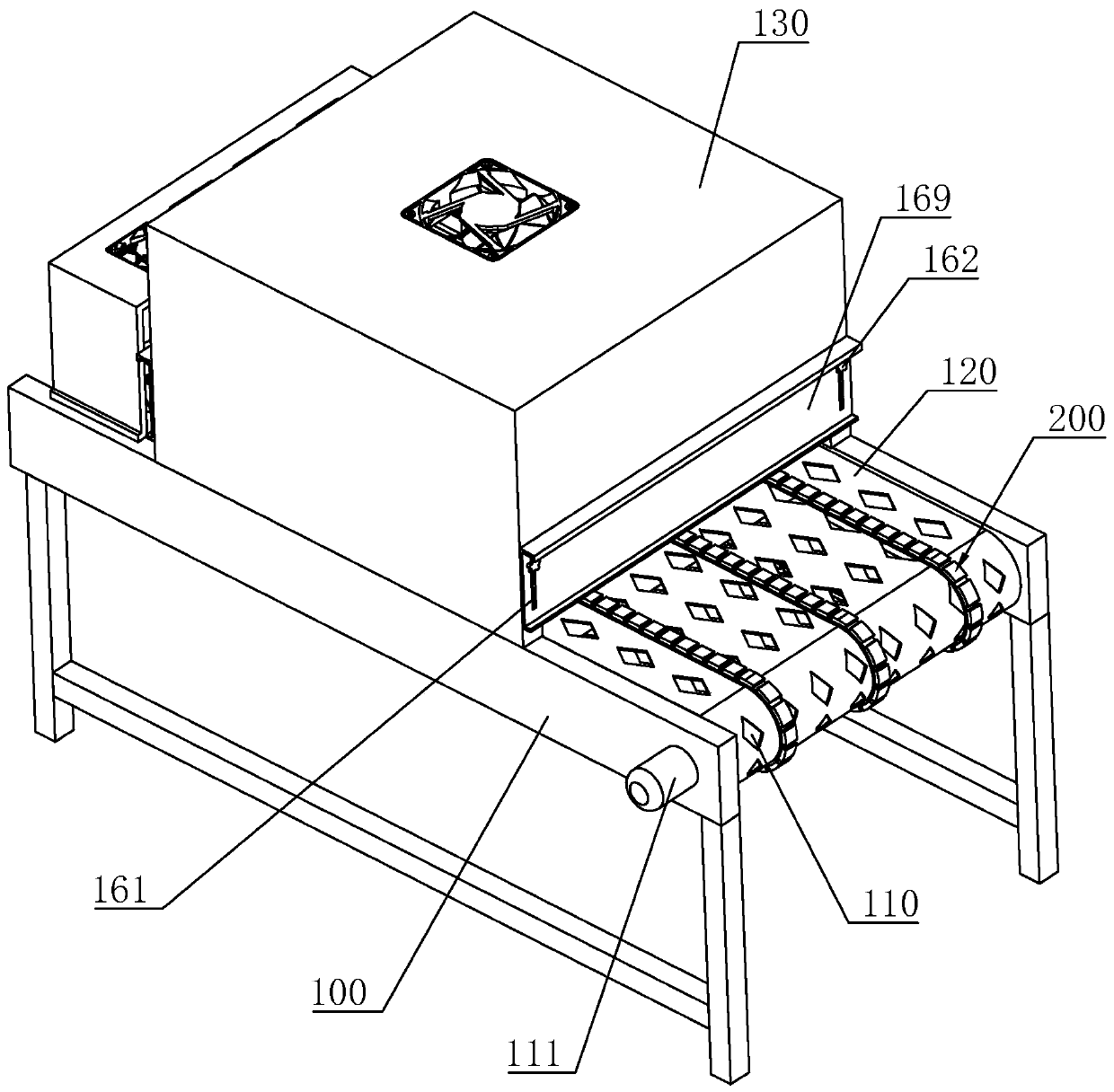
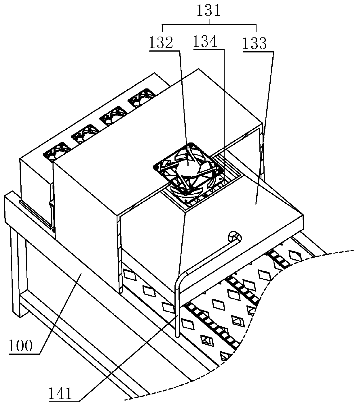
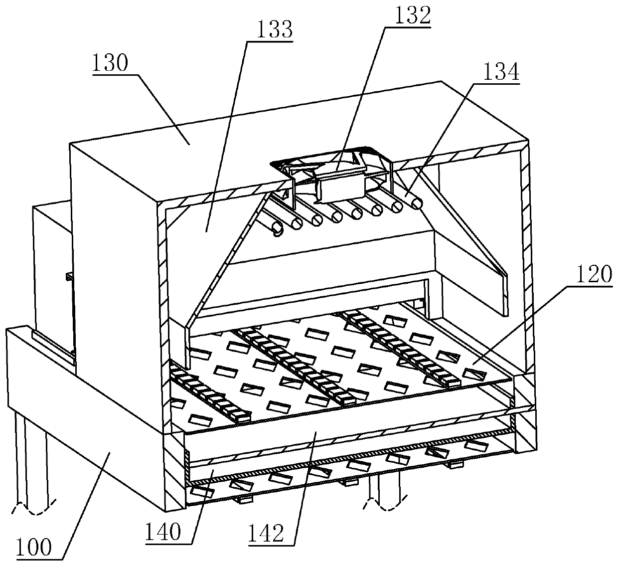
[0045] A tunnel furnace for terminal cables, refer to figure 1 , figure 2 , including a frame 100, both ends of the frame 100 are rotatably connected to conveying rollers 110, a conveying motor 111 is installed on the frame 100, and the output shaft of the conveying motor 111 is fixedly connected to one of the conveying rollers 110. The conveying roller 110 is sheathed with a conveying net 120 for conveying the wire, and in this embodiment the conveying net 120 is a stainless steel mesh chain. A drying box 130 is fixed in the middle of the frame 100 by bolts, and a drying device 131 is arranged in the drying box 130 . After placing the terminal cables covered with heat-shrinkable tubes on the conveying network 120, they are driven by the conveying roller 110 into the drying box 130, and the terminal cables are heated by the drying device 131, so that the h...


PUM


Abstract

The invention relates to the technical field of terminal wire processing and relates to a tunnel furnace for a terminal cable and a use method of the tunnel furnace. According to the main scheme, thetunnel furnace for the terminal cable comprises a machine frame; two ends of the machine frame are rotatably connected with conveying rollers; a conveying net is arranged on each conveying roller in asleeving way; a drying box is arranged on the middle part of the machine frame; a drying device is arranged in the drying box; and blocking pieces each for driving one end of a wire to be far away from one side of the conveying net is arranged on the conveying net. The tunnel furnace for the terminal cable has the following effects: one end of each wire is connected with the corresponding blocking piece, so that the end can be far away from the conveying net and is not in contact with the conveying net; when the conveying net conveys the wires into the drying box, hot air shrinks a heat shrinking tube and the wire at the other end of the machine frame can fall off successfully, so that the possibility of adhesion is reduced and feeding is facilitated.

Description

technical field [0001] The invention relates to the technical field of terminal wire processing, in particular to a tunnel furnace for terminal cable wires and a method for using the same. Background technique [0002] Wire and cable are used to transmit electric (magnetic) energy, information and wire products to realize electromagnetic energy conversion. In the broad sense, wires and cables are also referred to as cables for short. In the narrow sense, cables refer to insulated cables, which can be defined as: a collection composed of the following parts; one or more insulated cores, and their respective possible coatings. Protective layer and outer sheath. [0003] In the existing technology, when ordinary cables are processed into terminal cables, the coiled cables are first cut into several sections of equal length by a wire cutting machine. At this time, the wire cores in the cables are exposed, and the terminals need to be sleeved on one of the ends. , and the termi...

Claims


Application Information

Patent Timeline
IPC IPC(8): B29C65/68B29C63/42B29C35/04B29C35/00
CPCB29C35/002B29C35/045B29C63/42B29C65/68B29C2035/046
Inventor 罗文忠张巧梅
Owner 深圳市新都丰电子有限公司
Why Eureka
Try Eureka