Super-capacitor energy storage system for vehicle, rail vehicle and cooling method of super-capacitor energy storage system for vehicle

An energy storage system and super capacitor technology, applied in the field of rail vehicles, can solve the problems of complex docking structure between the carriage and the energy storage system, and the upper and lower super capacitor modules cannot achieve the same cooling effect, and achieve the effect of simplifying the structure.

Active Publication Date: 2020-04-28
NINGBO CRRC NEW ENERGY TECH CO LTD
View PDF5 Cites 3 Cited by
  • Summary
  • Abstract
  • Description
  • Claims
  • Application Information

AI Technical Summary

Problems solved by technology

[0004] Aiming at the above-mentioned deficiencies of the prior art, the technical problem to be solved by the present invention is to propose a supercapacitor energy storage system for vehicles, a cooling method for rail vehicles and supercapacitor energy storage systems for vehicles, which is used to solve the problem of upper and lower energy storage systems in the energy storage system. The problem that the supercapacitor module cannot achieve the same cooling effect and the problem of the complex docking structure between the compartment and the energy storage system

Method used


Image

  • Super-capacitor energy storage system for vehicle, rail vehicle and cooling method of super-capacitor energy storage system for vehicle
  • Super-capacitor energy storage system for vehicle, rail vehicle and cooling method of super-capacitor energy storage system for vehicle
  • Super-capacitor energy storage system for vehicle, rail vehicle and cooling method of super-capacitor energy storage system for vehicle

Examples


Embodiment 1

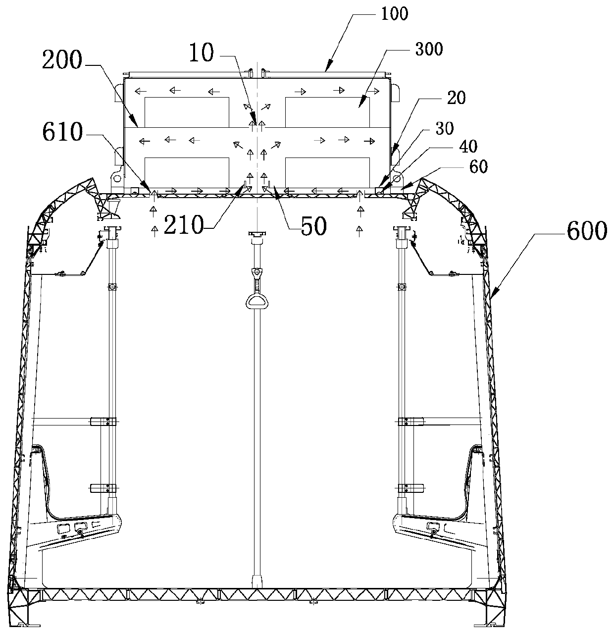
[0031] A supercapacitor energy storage system for a vehicle, comprising an energy storage cabinet 100, a plurality of slave control detection units 400, a master control unit 500, a plurality of mounting plates 200 arranged in the energy storage cabinet 100 and mounted on the installation A plurality of supercapacitor modules 300 on the board 200; the middle part of the energy storage cabinet 100 is provided with an air duct 10 connected with the interior of the energy storage cabinet 100, and the air duct 10 separates the plurality of installation plates 200 into There are two groups on the left and right, and the mounting plates 200 in each group are arranged up and down; the left and right sides of the energy storage cabinet 100 are respectively provided with a plurality of fans, and the bottom of the energy storage cabinet 100 protrudes from the bottom of the energy storage cabinet 100 with a sealing groove 30 in a circle , the seal groove 30 is provided with a seal gasket ...

Embodiment 2

[0048] A rail vehicle includes an energy storage system and a carriage 600; the energy storage system is located on the top of the carriage 600, and the carriage 600 directly supports the energy storage system.

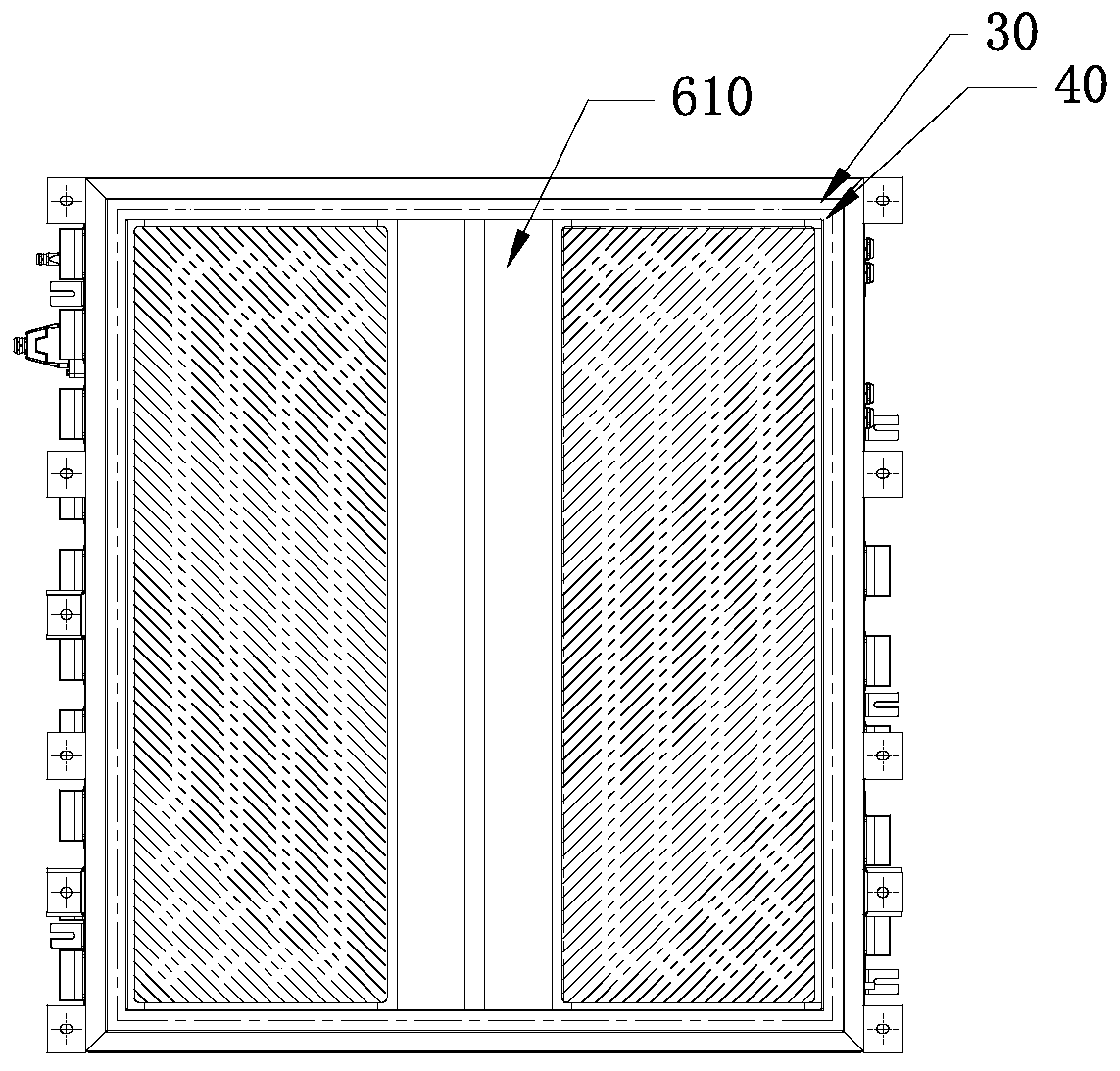
[0049] The top of the compartment 600 is provided with an air outlet 610 ; the energy storage system is covered on the air outlet 610 of the compartment 600 , specifically by utilizing the wind discharged from the compartment 600 to cool the energy storage system.

[0050] The top of the compartment 600 is in contact with the sealing groove 30 in the energy storage cabinet 100 and forms a cavity with the bottom layer of the energy storage cabinet 100 , and the cavity communicates with the air outlet 610 and the air duct 10 at the same time.

[0051] In this embodiment, the bottom layer of the energy storage cabinet 100 specifically includes two mounting plates 200, wherein the sealing groove 30 protrudes from the bottom layer of the energy storage cabinet 100, and the ...

Embodiment 3

[0057] A cooling control method for a supercapacitor energy storage system for a vehicle, comprising the following steps:

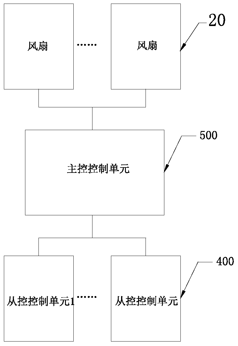
[0058] S1, detecting the temperature of the supercapacitor module 300 through the slave control unit and sending it to the master control unit 500 in real time;

[0059] S2, judging the temperature of the supercapacitor module 300, and controlling the number of fans corresponding to the temperature in the supercapacitor module 300;

[0060] S3, when the temperature is still rising after the preset fan is turned on, the main control unit 500 controls to continue to increase the number of fans until the temperature is maintained within the preset range. If the temperature exceeds the preset range, the The main control unit 500 controls the circuit breaker to open.

[0061] When the supercapacitor module 300 is powered, it is easy to generate heat. In this embodiment, the temperature of the supercapacitor module 300 is monitored by the slave control unit, a...


PUM


Abstract

The invention discloses a super-capacitor energy storage system for a vehicle, a rail vehicle and a cooling method of the super-capacitor energy storage system for the vehicle, and belongs to the technical field of rail vehicles. The rail vehicle comprises the energy storage system and a carriage; an air outlet is formed in the top of the carriage; and the top of the carriage makes contact with asealing groove in an energy storage cabinet body, and a cavity is defined by the top of the carriage and the bottom layer of the energy storage cabinet body and communicated with the air outlet and anair duct at the same time. When super-capacitor modules in the energy storage cabinet body are cooled, cooling air is shunted from the air duct, and the super-capacitor modules located on the upper layer and the lower layer of the energy storage cabinet body are cooled at the same time, so that the super-capacitor modules on the upper layer and the lower layer in the energy storage cabinet body almost obtain the same cooling effect; and in the rail vehicle, the energy storage system is directly placed at the top of the carriage, the air outlet is located in the ring of the sealing groove, sobutt joint of the energy storage system and the air outlet of the carriage is achieved, and the structures of the air outlet and a butt joint opening in the energy storage system are greatly simplified.

Description

technical field [0001] The invention relates to the technical field of rail vehicles, in particular to a supercapacitor energy storage system for vehicles, a rail vehicle and a cooling method for the supercapacitor energy storage system for vehicles. Background technique [0002] At present, vehicles using supercapacitor energy storage are basically arranged on the top of the vehicle due to the small height of the vehicle bottom. On the one hand, the space on the top can be used, and on the other hand, the exhaust air inside the vehicle can be used to cool the supercapacitor system. [0003] In the current scheme, the air outlet of the vehicle is often directly connected to the air inlet of the energy storage power supply, forming a vertical relationship. For example, application number 201310375553.0, the invention discloses an energy storage power supply, including an energy storage power supply box with an air inlet and an air outlet, a mounting plate arranged in the ene...

Claims


Application Information

Patent Timeline
Patent Type & Authority Applications(China)
IPC IPC(8): B60L50/40H01G11/18B61C17/06H01G11/78
CPCB60L50/40H01G11/18B61C17/06H01G11/78B60L2200/26Y02E60/13Y02T30/00Y02T10/70
Inventor 邓谊柏阮殿波陈挺何灵李向东
Owner NINGBO CRRC NEW ENERGY TECH CO LTD
Why Eureka
Try Eureka