Supercharge Your Innovation With Domain-Expert AI Agents!

Turnover device of vehicle-mounted display

A vehicle-mounted display and flipping device technology, which is applied to vehicle parts, transportation and packaging, can solve the problems of display board and flat frame acceleration impact, worm gear damage, etc., and achieve improved reliability, improved service life, and compact structure Effect

Pending Publication Date: 2020-04-28
XIAMEN XINSHENYUE ELECTROMECHANICAL
View PDF0 Cites 2 Cited by
  • Summary
  • Abstract
  • Description
  • Claims
  • Application Information

AI Technical Summary

Problems solved by technology

However, when the vehicle encounters bumps while driving, the display board and the flat frame will be subject to a sharp acceleration impact. Once this impact is superimposed on the gravity moment of the display board and the flat frame, exceeding the locking torque of the worm gear in the geared motor, it may damage to the worm gear

Method used


Image

  • Turnover device of vehicle-mounted display
  • Turnover device of vehicle-mounted display
  • Turnover device of vehicle-mounted display

Examples


Embodiment 1

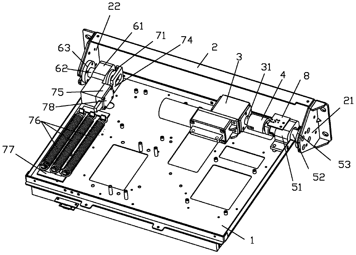
[0064] For the overturning device of the vehicle-mounted display of embodiment one, please refer to figure 1 . The overturning device includes a connecting frame and a mounting frame 2, and the connecting frame is, for example, a flat frame 1. Tablet 1 and display panel ( figure 1 Not shown in ) is connected to the back, the connection is fixed.

[0065] Mounting frame 2 is fixed on the car roof, and its left and right ends are respectively provided with the right lug 21 and the left lug 22 that protrude downwards. On the flat frame 1, a side near the mounting frame 2 is fixedly installed with a left rotating frame part, a driving mechanism and a right rotating frame part in sequence, the left rotating frame part includes a left rotating frame 61, and the right rotating frame part includes a right rotating frame 51.

[0066] The driving mechanism is mounted on the connecting frame and connected to the mounting frame 2 through transmission. If the driving mechanism includes ...

Embodiment 2

[0083] For the structure of the turning device of the vehicle-mounted display of embodiment two, please refer to Figure 7 . The overturning device has a connecting frame and a mounting frame 2, and the connecting frame includes a flat frame 1. Tablet 1 and display panel ( Figure 7 not shown in the back) connected to the back. Mounting frame 2 is fixed on the car roof, and its left and right ends are respectively provided with the right lug 21 and the left lug 22 that protrude downwards. One side near the mounting frame 2 on the flat frame 1 is fixedly installed with a left rotating frame part, a driving mechanism and a right rotating frame part in sequence, the left rotating frame part includes a left rotating frame 61, and the right rotating frame part includes a right rotating frame 51.

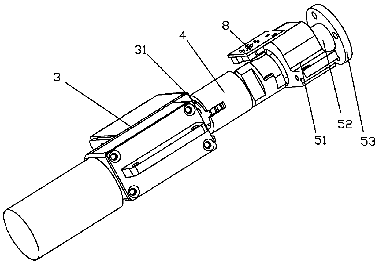
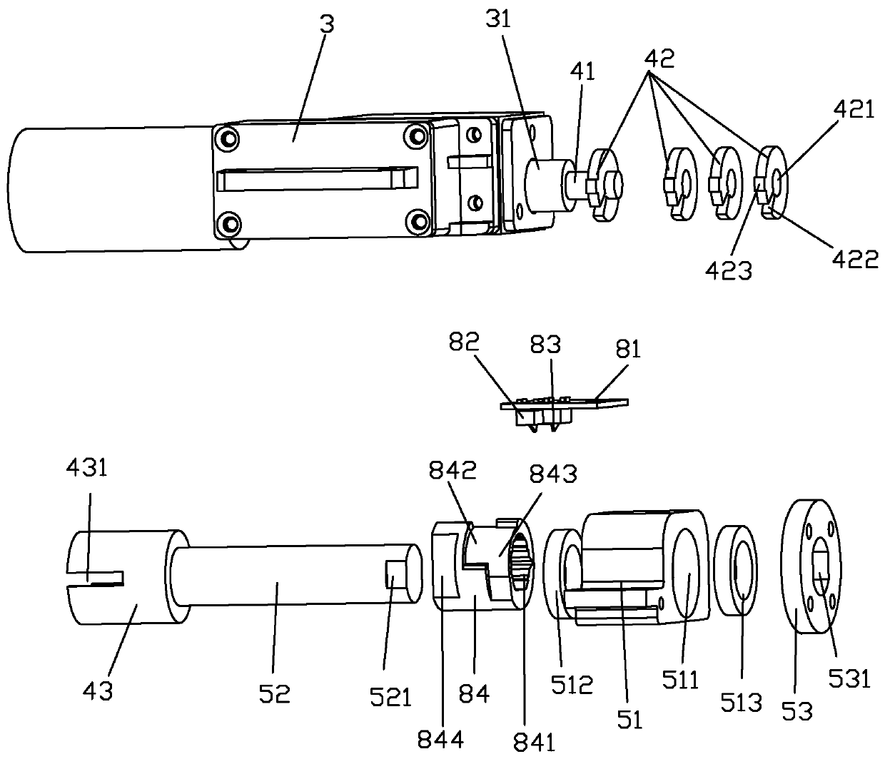
[0084] The drive mechanism includes a geared motor 3 , and the output shaft 31 of the geared motor 3 is coaxially connected to a right fixed shaft 52 sleeved on a right rotating frame ...

Embodiment 3

[0093] It differs from the structure of the turning device of the vehicle-mounted display in Embodiment 1 in that:

[0094] Please see Figure 10 , the driving mechanism and the gravity balance mechanism are respectively arranged on both sides of the flat frame 1, such as being respectively located on the right side and the left side, thereby reducing the thickness of the flat frame, making the combined thickness of the display and the flat frame thinner, reasonable layout, and compact structure. The driving mechanism is fixedly installed on the right side of the mounting frame 2, for example, it can be fixedly mounted on the mounting frame 2 ( Figure 10 (not shown in the middle) on the right lug, or directly fixedly installed on the mounting frame 2. The driving mechanism is connected to the flat frame 1 through transmission to drive the flat frame 1 to rotate around the rotating shaft. As required, the drive mechanism includes a motor 3 with a built-in clutch and a drive ...


PUM


Abstract

The invention discloses a turnover device of a vehicle-mounted display. The turnover device comprises two frame bodies, an eccentric part, a movable part and an elastic mechanism. The two frame bodiesare respectively a mounting frame and a connecting frame, a rotating part and a rotating frame part are respectively arranged on the two frame bodies, and the rotating part and the rotating frame part can rotate relatively. The eccentric part and the rotating part are relatively fixed, and the eccentric part is eccentrically arranged relative to the relative rotating axis of the rotating part andthe rotating frame part; the movable part and the rotary frame part can move relatively; the elastic mechanism is connected with the movable part and can generate elastic force applied to the movablepart, the movable part makes contact with the eccentric part under the action of the elastic force, and the eccentric part bears acting force applied by the movable part. Gravity moment generated bygravity of the display panel and the flat plate frame can be counteracted in real time, and the motor is protected.

Description

technical field [0001] The invention relates to components of a vehicle display, in particular to a turning device for a vehicle display. Background technique [0002] Existing vehicle-mounted display is usually installed on the ceiling in the car, and in order to reduce taking up the space in the car, display, such as liquid crystal screen (hereinafter referred to as the display panel) is installed on the turning device. This overturning device has a mounting bracket fixed on the car roof, and a flat frame installed on the back side of the display panel. The flat shelf of the overturning device is turned up and collected at ordinary times, so that the display surface of the display panel is attached to the ceiling in the car. During use, the flat frame of the turning device is turned down, so that the display panel is erected or nearly erected (illustrated in the erected state below). [0003] In a typical overturning device, rotating frames are respectively arranged on th...

Claims


Application Information

Patent Timeline
Patent Type & Authority Applications(China)
IPC IPC(8): B60R11/02
CPCB60R11/0235B60R2011/0028B60R2011/0092
Inventor 巫华志
Owner XIAMEN XINSHENYUE ELECTROMECHANICAL
Features
  • R&D
  • Intellectual Property
  • Life Sciences
  • Materials
  • Tech Scout
  • Unparalleled Data Quality
  • Higher Quality Content
  • 60% Fewer Hallucinations
Learn More