
Automatic car washer

A car washing machine and automatic technology, which is applied in the field of vehicle cleaning, can solve the problems of time-consuming and laborious, cumbersome disassembly and assembly process, and achieve the effects of ensuring stability, quick disassembly, improving disassembly and assembly efficiency and convenience

Pending Publication Date: 2020-04-28
宁波昊天智能设备科技有限公司
View PDF0 Cites 0 Cited by
  • Summary
  • Abstract
  • Description
  • Claims
  • Application Information

AI Technical Summary

Problems solved by technology

[0003] However, the traditional wheel brush needs to be installed on the output shaft of the drive motor through a coupling. The entire disassembly process is cumbersome, time-consuming and laborious, so there is still room for improvement.

Method used


Image

  • Automatic car washer
  • Automatic car washer
  • Automatic car washer

Examples


Embodiment Construction

[0020] The present invention will be further described in detail below in conjunction with the accompanying drawings and embodiments.

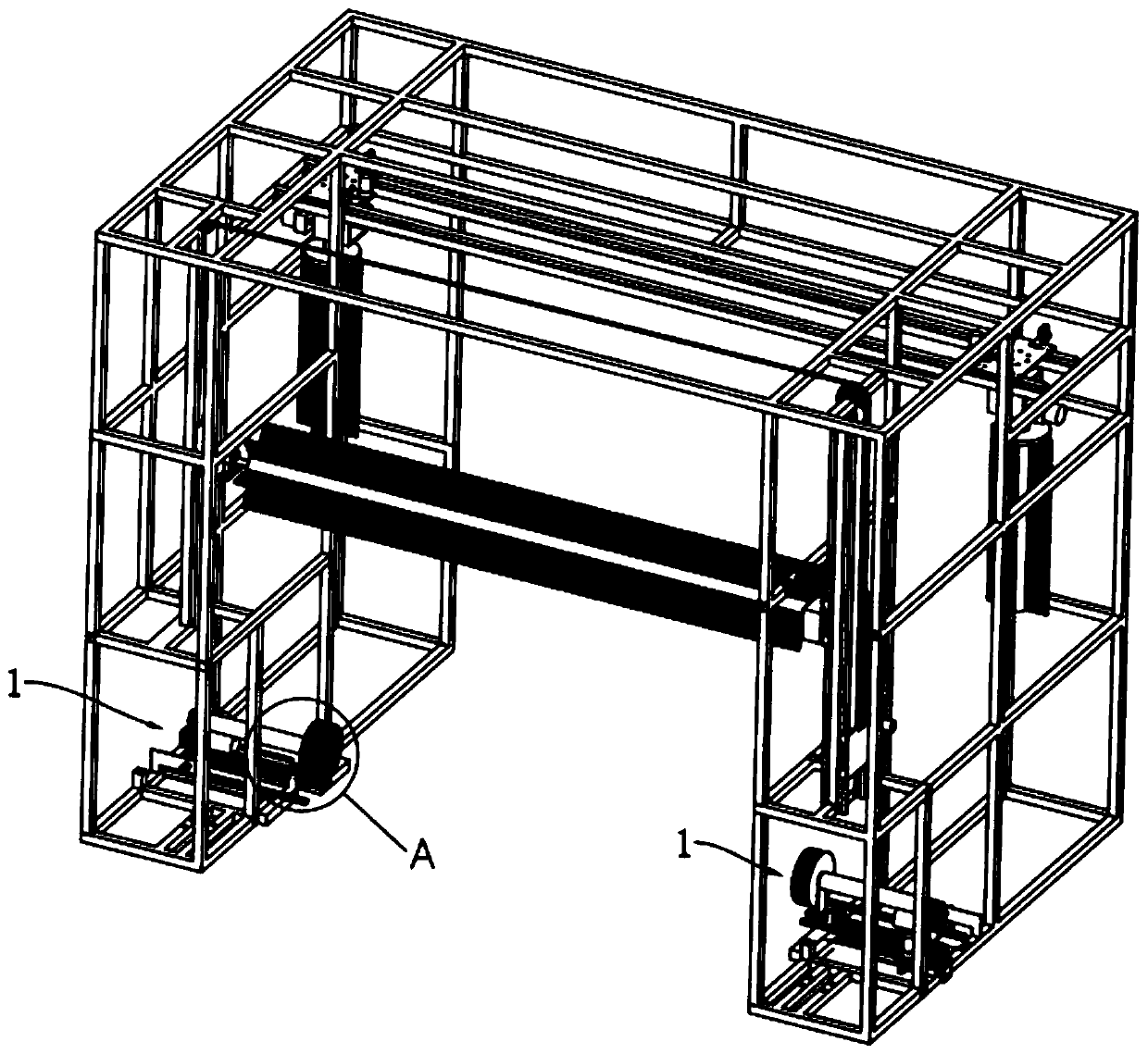
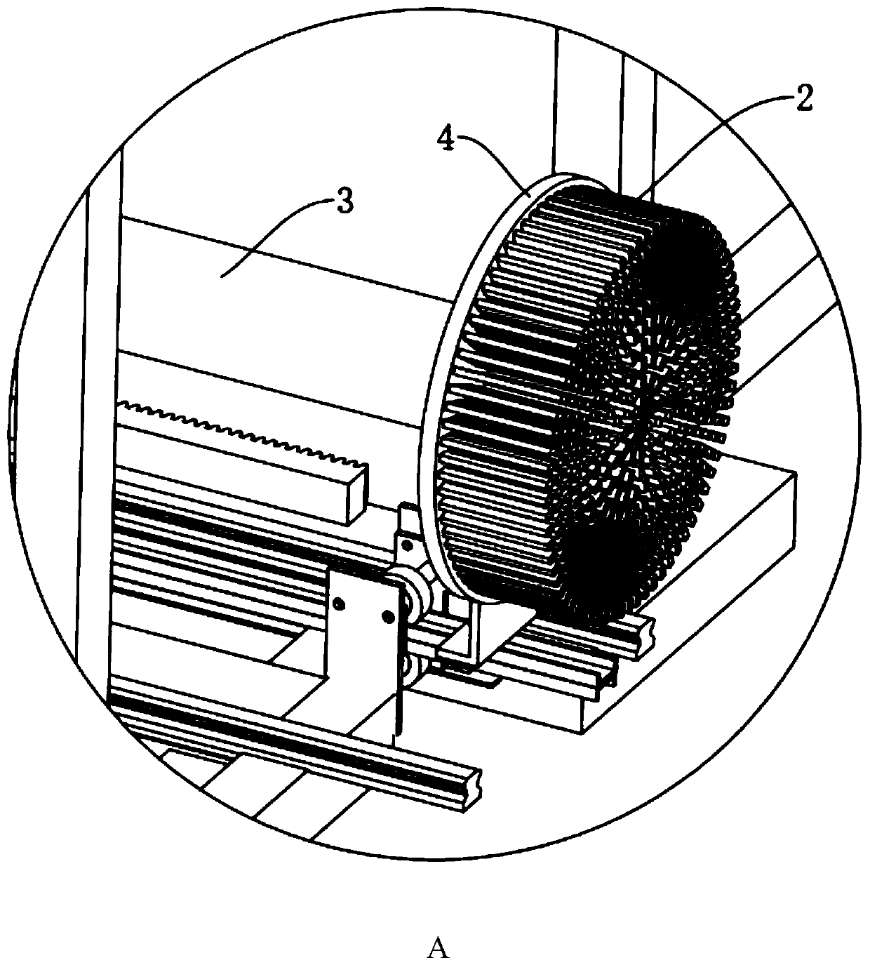
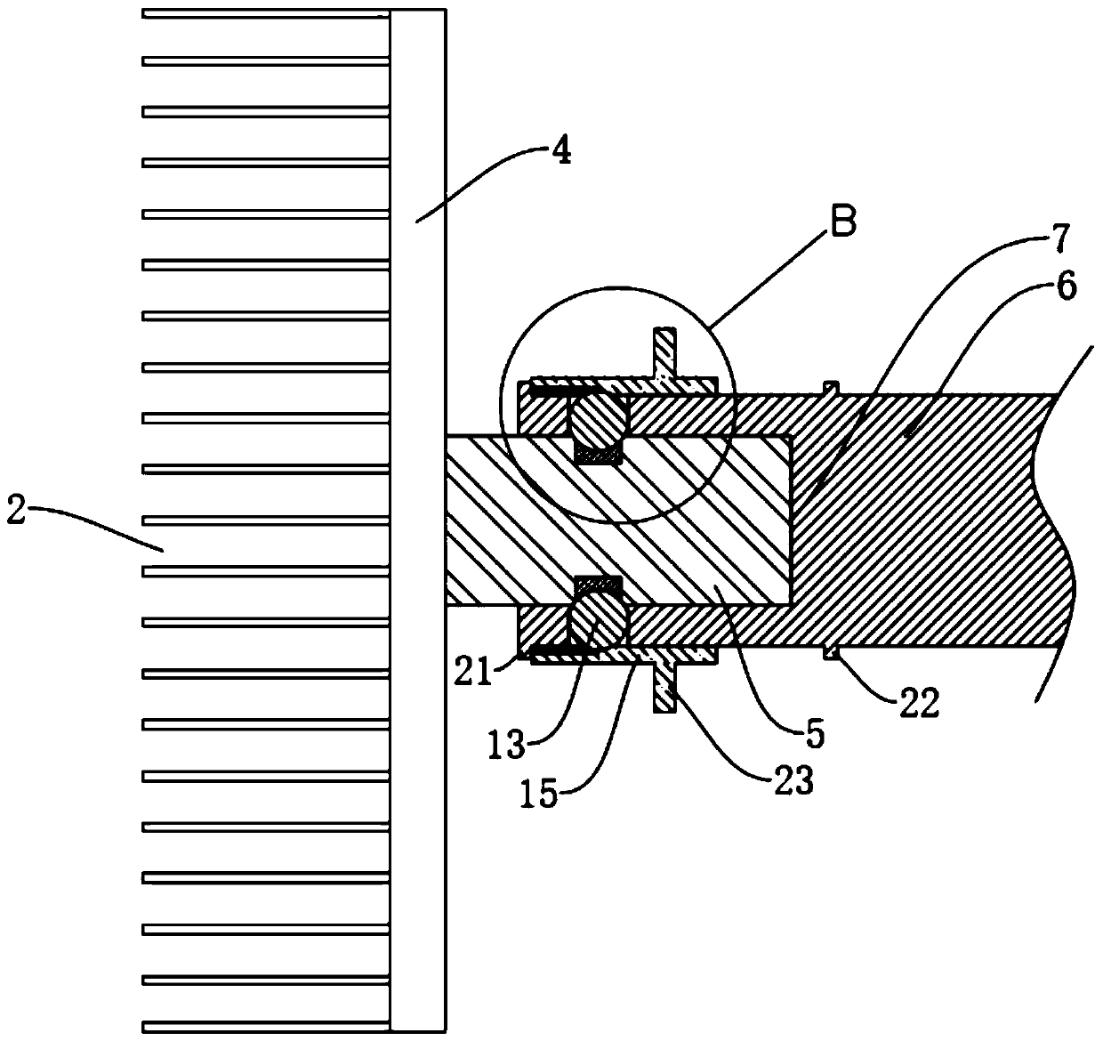
[0021] Such as Figure 1 to Figure 5 As shown, an automatic car washing machine disclosed in this embodiment includes a wheel brush system 1. The wheel brush system 1 includes a wheel brush 2 and a drive motor 3. A connecting shaft 5 extends vertically from the center of the chassis 4 of the wheel brush 2. The connecting shaft 5 is preferably cylindrical. The end face of the output shaft 6 of the drive motor 3 is provided with a slot 7 for connecting the connecting shaft 5. The slot 7 is preferably cylindrical, and its internal space size is adapted to the size of the connecting shaft 5, so that the connecting shaft 5 can be connected with the plugging shaft. Groove 7 is a tight fit. The outer wall of the connecting shaft 5 is provided with an outer limit plane 8 along its length direction, and the inner wall of the slot 7 is provided with a...


PUM


Abstract

The invention relates to the technical field of vehicle cleaning, and discloses an automatic car washer. A plurality of ball grooves are annularly formed in an output shaft in the circumferential direction of the output shaft, each ball groove comprises an outer opening formed in the outer wall of the output shaft and an inner opening communicated with an inserting groove, limiting balls are contained in the ball grooves, the sizes of the outer openings and the inner openings are smaller than the ball diameters of the limiting balls, and annular clamping grooves for clamping the spherical surfaces of the limiting balls are annularly formed in the outer circumferential surface of a connecting shaft; and the output shaft is sleeved with a movable sleeve to press the limiting balls into the annular clamping groove. The limiting balls can move in the ball grooves, when the movable sleeve connected to the output shaft in a sleeving mode slides to the position covering the outer openings ofthe ball grooves, And the inner wall of the movable sleeve can squeeze the limiting balls inwards to make the spherical surfaces of the limiting balls clamped into the annular clamping groove, so theaxial position of the connecting shaft in the inserting groove is limited, and the connecting shaft cannot be separated from the output shaft in the process that a driving motor drives wheel brushes to operate, thereby the stability of the wheel brushes in the operation process is guaranteed.

Description

technical field [0001] The invention relates to the technical field of vehicle cleaning, in particular to an automatic car washing machine. Background technique [0002] With the rapid development of the economy, the automobile industry has also developed rapidly. China is a country with a large population. The number of automobiles in China has reached more than 130 million. The automobile needs to be cleaned in the daily process. In the prior art, the car wash adopts manual cleaning and mechanical cleaning. In the way of manual cleaning, the work efficiency is low and the cost is high. Therefore, the use of mechanical cleaning is the development trend of modern car washing. Traditional car washing machines generally include racks, horizontal brush systems, vertical brush systems, wheel brush systems, spray systems, and air-drying systems. The wheel brush system of a traditional car washing machine is usually composed of a wheel brush and a drive motor. The output shaft of...

Claims


Application Information

Patent Timeline
IPC IPC(8): B60S3/06
CPCB60S3/06
Inventor 冉永亮
Owner 宁波昊天智能设备科技有限公司
Learn More