
Cross-blade type concrete buffering chute

A concrete and blade-type technology, which is applied in the direction of construction and infrastructure engineering, can solve the problems of damaged cap steel bars, segregation, etc., and achieve the effects of improving the overall rigidity, reducing the inclination, and controlling the flow rate of concrete

Pending Publication Date: 2020-04-28
CCTEB INFRASTRUCTURE CONSTR CO LTD +1
View PDF0 Cites 0 Cited by
  • Summary
  • Abstract
  • Description
  • Claims
  • Application Information

AI Technical Summary

Problems solved by technology

[0004] In order to overcome the technical defect in the prior art that when the concrete pouring height difference of the deep foundation pit of the cap is greater than 2m, the concrete flow rate is too fast to cause its segregation and damage the steel bars of the cap, the present invention provides a cross blade type buffer concrete chute, which can realize Automatically adjust the flow rate of concrete to solve the above technical problems

Method used


Image

  • Cross-blade type concrete buffering chute
  • Cross-blade type concrete buffering chute

Examples


Embodiment Construction

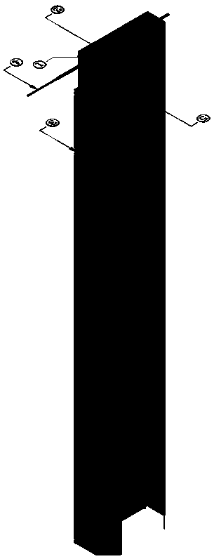
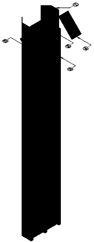
[0017] Such as figure 1 and figure 2 As shown, it is a schematic diagram of the overall structure of a cross-blade buffer concrete chute of the present invention, including a metal baffle 1, a U-shaped chute 2, square wood 3, a combined positioning steel plate 4 and cross blades 5, and the U-shaped chute 2 is open at both ends , rectangular metal baffles 1 are arranged symmetrically on both sides of the notch, and the two are fixed by welding to form a semi-closed structure. The combined positioning steel plate 4 is welded at the top, and the angle of the combined positioning steel plate 4 is pre-adjusted to determine the inclination angle of the U-shaped chute 2 when in use and control the flow rate of concrete in the U-shaped chute 2. The cross blades 5 are evenly arranged in an inverted triangle At the bottom of the U-shaped chute 2, the flow velocity of the concrete is effectively reduced by means of the automatic buffering of the inverted triangle structure of the cross...


PUM

PropertyMeasurementUnit
Thickness dimensionaaaaaaaaaa
Thicknessaaaaaaaaaa
Thicknessaaaaaaaaaa

Abstract

The invention discloses a cross-blade type concrete buffering chute. The chute comprises metal baffles, a U-shaped chute body, square timbers, combined positioning steel plates and cross blades, the rectangular metal baffles are symmetrically arranged on the two sides of a notch of the U-shaped chute body and fixed by welding, a welding angle is 45 degrees anticlockwise along the notch of the U-shaped chute body, the combined positioning steel plates are welded to the end of the U-shaped chute body, an inclination angle of the U-shaped chute body in use is determined by adjusting the combinedpositioning steel plates in advance, the flow speed of concrete in the U-shaped chute body is controlled, the cross blades are evenly arranged at the bottom of the U-shaped chute body in inverted-triangle shapes, and by means of automatic buffering of the inverted-triangle structures of the cross blades, the flow speed of the concrete is effectively reduced, and three square timbers evenly distributed in the transverse direction are installed on the back of the U-shaped chute body. The chute is simple in structure and capable of being repeatedly used, and the technical problems that when the concrete pouring height difference of a deep foundation pit of a bearing platform is larger than 2 m, the concrete flow speed is too high, and consequently the concrete segregation happens and bearingplatform steel bars are damaged are effectively solved.

Description

technical field [0001] The invention relates to the technical field of concrete construction for deep foundation pits of caps, in particular to a cross blade type buffer concrete chute. Background technique [0002] In the civil engineering industry, concrete is one of the most important engineering materials, and its performance has a profound impact on the quality of the entire engineering structure. Therefore, it is extremely critical to strictly control the quality of concrete during the concrete pouring process. When the concrete is too large and inconvenient to be transported safely, use the attachment chute (wooden or iron, semicircular, semi-quadrangle) to make the concrete slide down from high to low. This construction method can prevent the segregation of concrete due to the action of gravity , so that the quality of concrete is guaranteed. [0003] Existing chute devices mainly contain semicircular, Y-shaped, rotary, multi-opening, walking and combined types. It...

Claims


Application Information

Patent Timeline
IPC IPC(8): E02D15/02
CPCE02D15/02
Inventor 王宋华陈学松聂闯荆传奎刘鹏
Owner CCTEB INFRASTRUCTURE CONSTR CO LTD
Learn More