High pressure water pump

A high-pressure water pump and pump housing technology, applied in pump control, pump components, variable capacity pump components, etc., can solve the problems of unstable commutation, instability, affecting production efficiency, etc., to achieve compact size, space and parts saving , the effect of simple structure

Inactive Publication Date: 2020-04-28
宁波真格液压科技有限公司
View PDF6 Cites 2 Cited by
  • Summary
  • Abstract
  • Description
  • Claims
  • Application Information

AI Technical Summary

Problems solved by technology

For a long time, the research and development of domestic reciprocating high-pressure water pumps has been mainly based on the transformation of foreign technologies, and digestion and absorption have been carried out on the basis of the introduction of foreign technologies. However, the real core technology of high-pressure water pumps has not been mastered. The existing reciprocating high-pressure water pumps output pulses Large, unstable, and easy to get stuck under harsh working conditions, and the noise is loud during operation. In addition, most of the reversing valves that realize the reciprocating motion of the piston in the current reciprocating water pumps use electromagnetic reversing valves and displacement sensors to control the reversing valves. The sensor is controlled by the proximity switch, and the reversing is unstable and unreliable; the control circuit part of the reversing device is controlled by a circuit board, because the circuit board is a non-standard part, and it is difficult to manufacture and process, and it is very difficult to repair after damage ; If the existing reversing device is continuously energized for a long time, it is easy to damage small devices and cannot meet the requirements of long-term energization, which also affects production efficiency to a certain extent

Method used


Image

  • High pressure water pump
  • High pressure water pump
  • High pressure water pump

Examples


Embodiment Construction

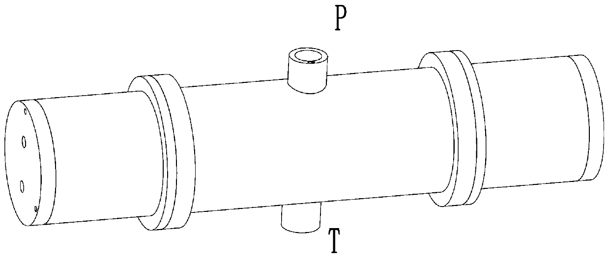
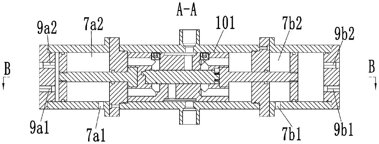
[0024] See Figure 1-23 As shown, a high-pressure water pump includes a pump body 1, which is provided with a left and right through mounting hole 101, a left end cover 6a is fixedly mounted on the left end of the pump body 1, and a right end cover 6b is fixedly mounted on the right end; A piston body 2 that moves left and right is slidingly connected to the mounting hole 101. A sliding guide hole 201 is provided on the piston body 2 along its movement direction. A sliding connection is provided between the left end cover 6a and the right end cover 6b. The anti-rotation guide slide bar 10 in the guide slide hole 201; a left pump casing 7a is fixedly installed on the left side of the left end cover 6a, and a left cover 9a is fixedly installed on the left end of the left pump casing 7a. A right pump casing 7b is fixedly installed on the right side of the right end cover 6b, and a right cover 9b is fixedly installed on the right end of the right pump casing 7b; the left end of the ...


PUM


Abstract

The invention discloses a high pressure water pump. The high pressure water pump comprises a pump body, and a left end cover is fixedly installed at the left end of the pump body and a right end coveris fixedly installed at the right end of the pump body. A piston body is slidably connected into the pump body. A left pump case is fixedly installed on the left side of the left end cover, and a left sealing cover is fixedly installed at the left end of the left pump case. A right pump case is fixedly installed on the right side of the right end cover, and a right sealing cover is fixedly installed at the right end of the right pump case. A left connecting rod is fixedly installed at the left end of the piston body, and a right connecting rod is fixedly installed at the right end of the piston body. A left piston is arranged at the left end of the left connecting rod, and a right piston is arranged at the right end of the right connecting rod. A P oil port and a T oil port are formed inthe outer side surface of the pump body. The piston body is internally provided with a control component for controlling the piston body to move left and right in a mounting hole. The high pressure water pump is simple in structure and small in size, and can control the automatic back and forth movement of the piston body without electric control.

Description

Technical field [0001] The invention belongs to the technical field of water pumps, and specifically relates to a high-pressure water pump. Background technique [0002] A water pump is a machine that transports liquids. It transfers the mechanical energy of the prime mover or other external energy to the liquid to increase the liquid energy. Positive displacement pumps use changes in the volume of their working chambers to transfer energy; reciprocating high-pressure water pumps are commonly used high-pressure water power source equipment in modern industry. For a long time, the research and development of domestic reciprocating high-pressure water pumps has mainly focused on transforming foreign technology, digesting and absorbing on the basis of introducing foreign technology, but has not mastered the real core technology of high-pressure water pumps. The existing reciprocating high-pressure water pumps output pulses. Large, unstable, and easy to get stuck under severe worki...

Claims


Application Information

Patent Timeline
Patent Type & Authority Applications(China)
IPC IPC(8): F04B53/14F04B53/16F04B53/10F04B49/22
CPCF04B49/22F04B53/10F04B53/14F04B53/16
Inventor 邵立坤
Owner 宁波真格液压科技有限公司
Why Eureka
Try Eureka