Servo valve automatic centering device and method

An automatic centering and servo valve technology, applied in the field of servo valves, can solve the problems of low precision and low efficiency of manual centering of servo valves, achieve controllable accuracy, improve centering efficiency and precision, and save operating space Effect

Active Publication Date: 2020-04-28
BEIJING MECHANICAL EQUIP INST
View PDF7 Cites 1 Cited by
  • Summary
  • Abstract
  • Description
  • Claims
  • Application Information

AI Technical Summary

Problems solved by technology

[0008] In view of the above analysis, the embodiment of the present invention aims to provide a servo valve automatic centering device and a centering method to solve the problems of low efficiency and low precision of servo valve manual centering in the prior art

Method used


Image

  • Servo valve automatic centering device and method
  • Servo valve automatic centering device and method
  • Servo valve automatic centering device and method

Examples


Embodiment 1

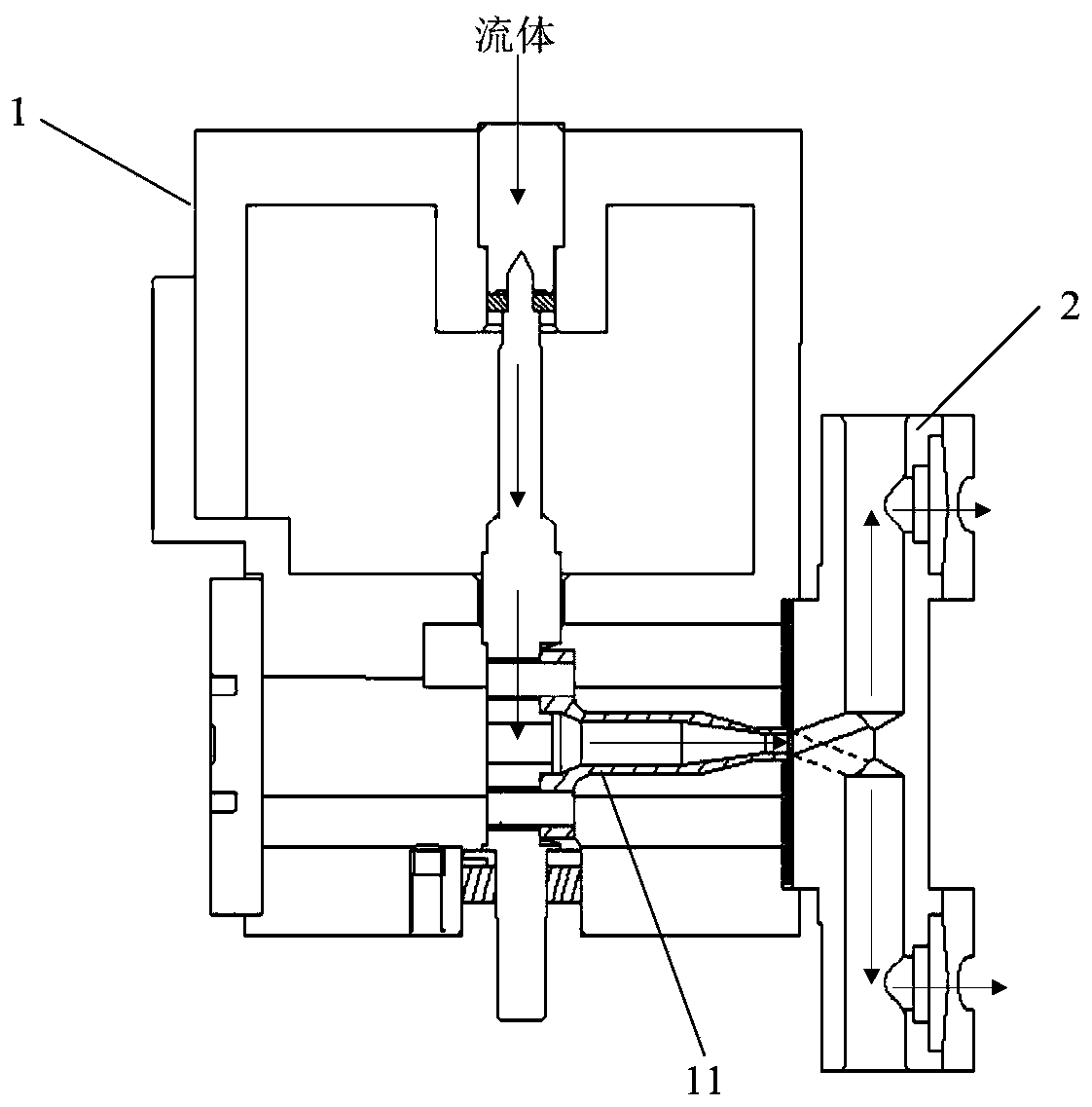
[0050] This embodiment provides an automatic centering device for a servo valve, which is used to feed air into the center of the valve 11 of the servo valve body 1 (the servo valve includes the servo valve body 1 and the receiver 2) and the two airflow channels of the receiver 2 The middle positions of the air inlets (hereinafter referred to as air inlet A and air inlet B) are aligned, and this process is referred to as valve centering.

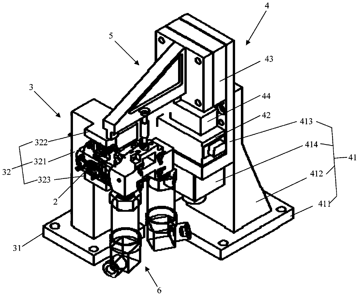
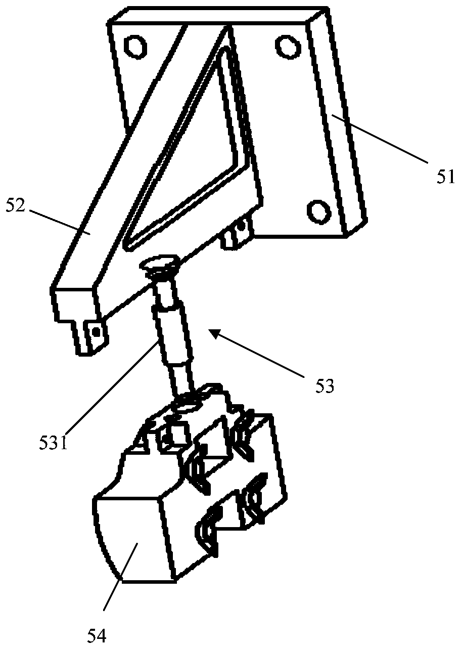
[0051] Such as Figure 1-Figure 4As shown, the servo valve automatic centering device (hereinafter referred to as the centering device) includes a mounting seat 3, a servo unit 4, a connecting rod unit 5, a detection unit 6 and a control unit 7, and the servo valve body 1 is set on the mounting seat 3 , the servo unit 4 is connected with the receiver 2 of the servo valve through the connecting rod unit 5, so that the receiver 2 can move relative to the servo valve body 1 with the connecting rod unit 5, the servo unit 4, the detection unit 6 ...

Embodiment 2

[0077] This embodiment provides an automatic centering method for a servo valve, using the above-mentioned servo valve automatic device for automatic centering, including the following steps:

[0078] Step 1: Install the servo valve body 1 on the mounting seat 3, loosen the positioning bolts connecting the receiver 2 and the servo valve body 1, and the receiver 2 can move relative to the servo valve body 1 under the action of external force;

[0079] Specifically, the servo valve body 1 is installed between the upper plate 322 and the lower plate 323, and is connected with the outlet of the air flow channel of the column 321, so that the servo valve body 1 can be connected with the external air source; the positioning bolt makes the receiver 2 and the servo valve The body 1 is connected and can move relative to the servo valve body 1;

[0080] Step 2: Connect the connecting rod unit 5 with the receiver 2, and connect the detection unit 6 with the air outlet A and the air outle...


PUM


Abstract

The invention relates to a servo valve automatic centering device and method, and belongs to the technical field of servo valves. The problems that in the prior art, the servo valve manual centering efficiency is low, and precision is not high are solved. The servo valve automatic centering device comprises an installing base, a servo unit, a connecting rod unit, a detection unit and a control unit. A servo valve body of the servo valve is detachably installed on the installing base. The servo unit is connected with a receiver of the servo valve through the connecting rod unit, and the receiver can move relative to the servo valve body. The detection unit is used for detecting the air pressure value of two airflow channel air outlets of the receiver in real time and transmitting the testedair pressure data to the control unit in real time. The control unit controls the servo unit to adjust the position of the receiver according to the air pressure data tested in real time. The servo unit is controlled to adjust the position of the receiver, manual adjustment is not needed in the whole process, the process is automatic and controllable, and the centering efficiency and precision can be effectively improved.

Description

technical field [0001] The invention relates to the technical field of servo valves, in particular to an automatic centering device and a centering method for a servo valve. Background technique [0002] The servo valve is the control part of the control device, and its main working principle is to realize the output of the control execution process by controlling the distribution of gas. The servo valve includes a servo valve body and a receiver. After the gas enters the servo valve, it flows into the gas nozzle in the servo valve body. By controlling the angle of the gas nozzle, the gas entering the two airflow channels of the receiver is distributed, and finally the actuator is pushed toward the corresponding action in the direction. [0003] In the initial state without giving instructions to the control device, theoretically the center of the air nozzle should be in the middle of the two airflow channels of the receiver. If the center of the air nozzle is too much to ...

Claims


Application Information

Patent Timeline
IPC IPC(8): F16K51/00B23P19/04
CPCF16K51/00B23P19/04
Inventor 童浩王凯任宏魏亚林程建安张晓凤
Owner BEIJING MECHANICAL EQUIP INST
Why Eureka
Try Eureka