
Hot-line work robot climbing device
A technology for live work and robots, which is applied in the direction of motor vehicles, transportation and packaging, overhead lines/cable equipment, etc., can solve the problems such as the difficulty of transporting live work robots to the operating position, and achieve stable connection, not easy to shake, and convenient disassembly Effect
- Summary
- Abstract
- Description
- Claims
- Application Information
AI Technical Summary
Problems solved by technology
Method used
Image

Examples
Embodiment 1
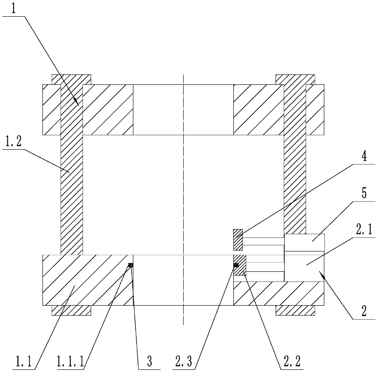
[0030] Such as figure 1 As shown, a climbing device for a live working robot includes a hoop device 1 and a clamping device 2. The clamping device 2 includes a clamping cylinder 2.1 and a clamping block 2.2. The clamping cylinder 2.1 is fixed on the hoop device 1. The clamping block 2.2 is fixed on the telescopic rod of the clamping cylinder 2.1, the side of the clamping block 2.2 close to the central axis of the hoop device 1 is a V-shaped structure, and the side of the clamping block 2.2 close to the central axis of the hoop device 1 is provided with a first A chute 2.3, the first chute 2.3 is provided with a ball 3; the hoop device 1 includes a hoop body 1.1, and the hoop body 1.1 includes two hoop semicircles, one end of the two hoop semicircles is hinged, and the two hoops The other end of the semicircle is clamped by the pin shaft structure; the inner side of the hoop body 1.1 is provided with a second chute 1.1.1, and a ball 3 is provided in the second chute 1.1.1.
[...
Embodiment 2
[0033] Such as figure 1 As shown, on the basis of Embodiment 1, the climbing device of the live working robot also includes a locking block 4 and a locking cylinder 5, the locking cylinder 5 is fixed on the hoop device 1, and the locking block 4 and the locking cylinder 5 The telescoping rod is fixed.
[0034] The above-mentioned locking block 4 is made of a material with a large friction coefficient such as rubber. When the locking block 4 is pressed against the utility pole, the hoop device 1 is locked and cannot move up and down and turn left and right relative to the utility pole, which is convenient for installation. The actuator on the hoop device 1 performs the next step.
Embodiment 3
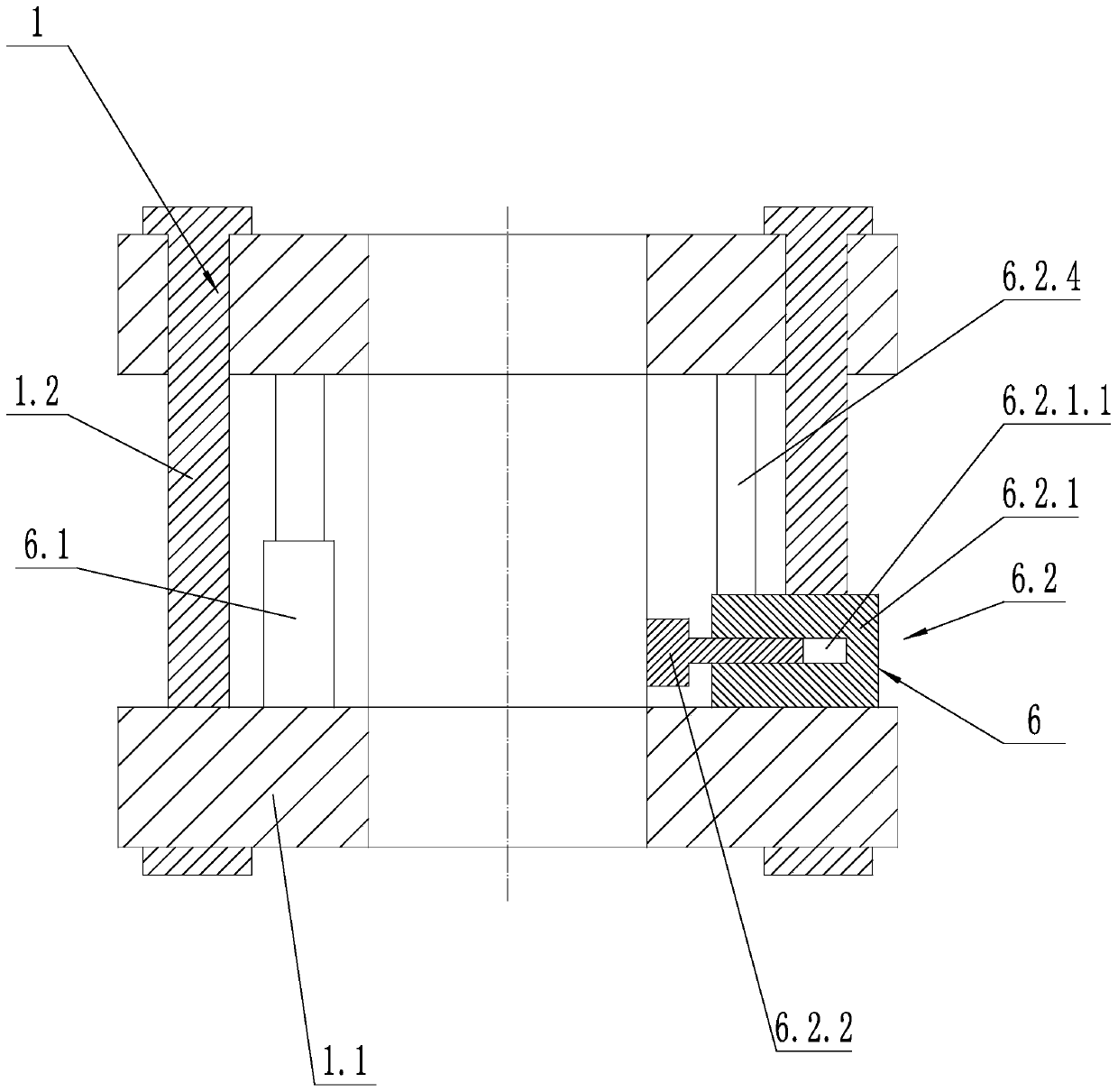
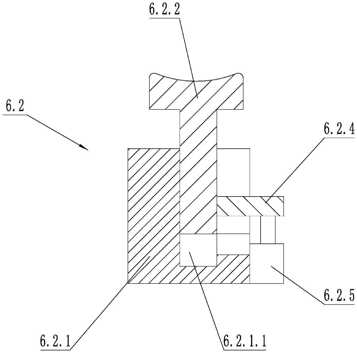
[0036] Such as figure 2 As shown, on the basis of Embodiment 1, the hoop device 1 includes two hoop bodies 1.1, and the two hoop bodies 1.1 are coaxially arranged up and down; the climbing device of the live working robot also includes a lifting structure 6, and the lifting structure 6 includes a lifting structure 6 Cylinder 6.1 and two locking structures 6.2 for clamping the utility pole, the cylinder body and telescopic rod of the lift cylinder 6.1 are respectively fixed with the upper and lower hoop bodies 1.1, and one end of the connecting rod 1.2 is fixed with one of the hoop bodies 1.1, The connecting rod 1.2 is fixedly and slidably connected with another hoop body 1.1. The hoop device 1 includes two hoop bodies 1.1 arranged coaxially up and down and connected by a connecting rod 1.2.
[0037] In the above technical solution, the two hoop bodies 1.1 are distributed up and down, which can ensure that the hoop device 1 is not easily shaken after being connected to the ut...
PUM
 Abstract
Description
Claims
Application Information