Packing device for pump shaft

A technology for pump shafts and packing glands, applied to parts, pumps, and pump components of pumping devices for elastic fluids, which can solve problems such as leakage, and achieve the effects of avoiding leakage, easy filling, and uniform compression deformation

Inactive Publication Date: 2020-05-01
朱晶
View PDF0 Cites 0 Cited by
  • Summary
  • Abstract
  • Description
  • Claims
  • Application Information

AI Technical Summary

Problems solved by technology

[0003] In order to solve the leakage problem caused by packing wear in the prior art, the present invention provides an automatic compensation packing sealing device for pumps, which can squeeze the packing before the packing wears to create a gap, and refill the gap after deformation

Method used


Image

  • Packing device for pump shaft

Examples


Embodiment Construction

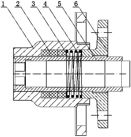
[0012] The specific embodiment of the present invention is described in further detail below in conjunction with accompanying drawing:

[0013] As shown in the figure, the automatic compensation shaft seal device for a pump includes a pump cover 1 , a packing 2 , a thrust plate 3 , a thrust spring 4 , a shaft sleeve 5 and a packing gland 6 . The shaft sleeve 5 is coaxially arranged in the pump cover 1 to form a cavity, and the cavity is tightly filled with packing 2, and the packing 2 is in close contact with the left convex surface of the pump cover 1 to seal, and the right end surface of the pump cover 1 is provided with a packing Gland 6, packing gland 6 is coaxially socketed on the shaft sleeve 5 through its central round hole, the head of the packing gland 6 extends into the inner cavity of the pump cover 1, the head of the packing gland 6 and the packing The two rooms are provided with a thrust spring 4, the left side of the thrust spring 4 is extruded by the thrust plat...


PUM


Abstract

The invention provides a self-compensating packing seal device for a pump so as to solve the problem of leakage caused by packing wear in the prior art. The packing device for a pump shaft comprises apump cover, a shaft sleeve, a thrust plate, a thrust spring, packing and a packing gland. The shaft sleeve is axially arranged in the pump cover and forms a cavity with the pump cover, the cavity isfilled with the packing which is in a contact seal state with a boss surface on the left side of the interior of the pump cover, the end face of the right side of the pump cover is connected with thepacking gland which is coaxially connected to the shaft sleeve in a sleeving manner through a central round hole, the head of the packing gland extends into an inner cavity of the pump cover, and thethrust spring and the thrust plate are arranged between the head of the packing gland and the packing.

Description

technical field [0001] The invention relates to the field of pump sealing, in particular to a packing device for a pump shaft. Background technique [0002] The shaft seal is a sealing device designed to prevent leakage between the pump shaft and the casing. Packing seals are widely used in pumps for conveying water media due to their simple structure, low price, and convenient maintenance. The principle of packing seal is that when the packing moves relative to each other, due to the plasticity of the packing, it generates radial force and is in close contact with the shaft. At the same time, the lubricant impregnated in the filler is squeezed out, forming an oil film between the contact surfaces. Since the contact state is not particularly uniform, a "boundary lubrication" state appears at the contact part, which is called "bearing effect"; while the uncontacted concave part forms a small oil groove with a thicker oil film, and the contact part and the non-contact part f...

Claims


Application Information

Patent Timeline
Patent Type & Authority Applications(China)
IPC IPC(8): F04D29/10
CPCF04D29/106
Inventor 朱晶张扬
Owner 朱晶
Why Eureka
Try Eureka