A fully automatic special tape coating machine

A kind of coating machine, fully automatic technology, applied in the direction of surface coating liquid device, coating, surface polishing machine tool, etc., can solve the problem of lack of substrate cleaning and polishing functions, poor substrate pretreatment, and work efficiency Low-level problems, to achieve the effect of improving fully automatic performance, convenient automatic replacement, and saving working time

Active Publication Date: 2021-04-09
安徽长正升科技有限公司
View PDF7 Cites 1 Cited by
  • Summary
  • Abstract
  • Description
  • Claims
  • Application Information

AI Technical Summary

Problems solved by technology

[0003] However, the existing tape coating machine is poor in pretreatment of the substrate, and does not have the function of cleaning and polishing the substrate. The existing special tape is rewound by a rewinding roller at a fixed position, and the rewinding is completed. Finally, it is necessary to stop the machine to unload the rewound special tapes one by one, and then insert the empty paper ring into the rewinding roller. The work efficiency is low and the time cost is high. Therefore, we propose a fully automatic special tape coating machine

Method used


Image

  • A fully automatic special tape coating machine
  • A fully automatic special tape coating machine
  • A fully automatic special tape coating machine

Examples


Embodiment 1

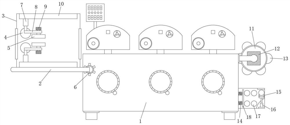
[0025] Such as figure 1 As shown, a fully automatic special tape coating machine includes a main body 1 of the tape coating machine, a load-bearing plate 2 is provided on one side of the main body 1 of the tape coating machine, and a clamping bolt 6 is welded at one end of the load-bearing plate 2, and the load-bearing plate 2 passes through the card The bolt 6 is clamped with the main body 1 of the tape coating machine, and the upper part of the load-bearing plate 2 is installed with the box body 3. The sliding device 10 is inlaid on both sides of the box body 3. The bottom of the sliding device 10 is equipped with an air pressure rod 7, and the bottom side of the air pressure rod 7 is The rotating roller 4 is installed, and the other side of the bottom of the air pressure rod 7 is welded with a connecting column 8, the bottom end of the connecting column 8 is equipped with a polishing plate 5, the upper end of the connecting column 8 is provided with a motor one 9, and the ou...

Embodiment 2

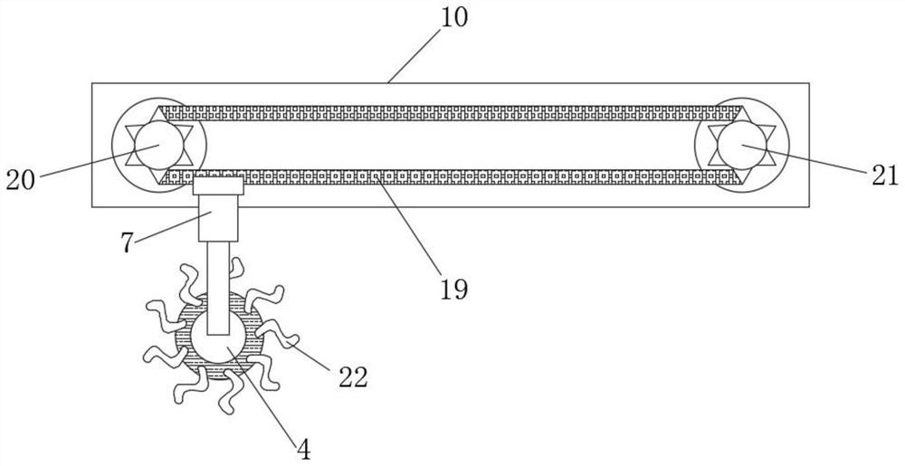
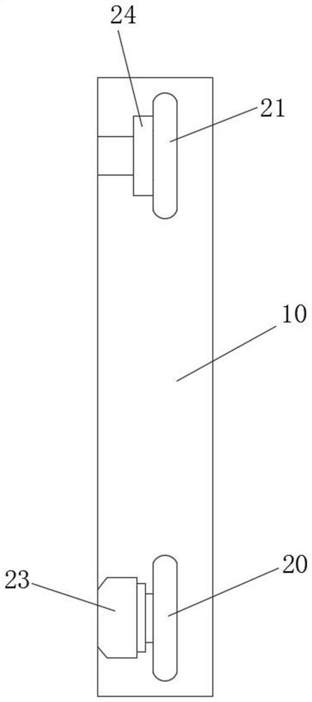
[0028] Such as Figure 1-3 As shown, one end of the sliding device 10 is provided with a gear one 20, and the other end of the sliding device 10 is provided with a gear two 21, the gear one 20 is externally meshed with the chain 19, the gear one 20 is meshed with the gear two 21 through the chain 19, and the chain One end of the bottom of 19 is welded with an air pressure rod 7, and the outside of the rotating roller 4 is bonded with a sponge brush 22, and one side of the gear one 20 is provided with a servo motor 23, and the output shaft of the servo motor 23 is connected with the gear one 20, and the gear one 20 is connected to the The sliding device 10 is connected, and a bearing 24 is installed on one side of the gear two 21, and the second gear 21 is connected with the sliding device 10 through the bearing 24.

[0029] In this embodiment, by setting the servo motor 23 and the chain 19, the air pressure rod 7 can be effectively moved inside the box body, and the cleaning a...

Embodiment 3

[0031] Such as figure 1 with Figure 4 As shown, a turntable 11 is installed at one end of the main body 1 of the adhesive tape coating machine, and a motor 2 12 is arranged on one side of the turntable 11. The side ring is provided with a hydraulic cylinder 25, and one end of the hydraulic cylinder 25 is fixedly connected to the motor 3 26, the output shaft of the motor 3 26 is connected to the slot 27, and the side of the slot 27 is connected to the winding roller 13. One end of the bottom of the main body 1 is equipped with a storage box 15, and the storage box 15 is located directly below the turntable 11. A spring 14 is installed on one side of the inner wall of the storage box 15, and one end of the spring 14 is welded with a push plate 18. The storage box 15 is provided with a storage box. Roller two 17, winding roller two 17 are positioned at push plate 18 one sides, and electric cylinder 16 is installed at one end of storage box 15 bottoms.

[0032] In this embodime...


PUM


Abstract

The invention discloses a full-automatic special tape coating machine, which comprises a main body of the tape coating machine, a load-bearing plate is arranged on one side of the main body of the tape coater, a clamping bolt is welded at one end of the load-bearing plate, and the load-bearing plate passes through The clamping bolt is clamped with the main body of the tape coating machine. The upper part of the load-bearing plate is equipped with a box. Both sides of the inside of the box are inlaid with sliding devices. The bottom of the sliding device is provided with an air pressure rod. Installed with turning rollers. The present invention pretreats the base material effectively by setting the air pressure rod and the polishing plate, the air pressure rod is convenient to adjust the distance between the sponge brush and the polishing plate The motor and chain can effectively make the air pressure rod move inside the box to better clean and polish. By setting the turntable and electric cylinder, the working efficiency of the tape coating machine can be effectively improved, and repeated replacement of the winding roller can be avoided, saving money. Working hours are suitable for being widely promoted and used.

Description

technical field [0001] The invention relates to an adhesive tape coating machine, in particular to an automatic special adhesive tape coating machine. Background technique [0002] There are two coating methods of the tape coating machine, one is to coat the photosensitive emulsion on the screen through multiple wet-on-wet operations; or add a drying process after each coating. It is a machine that quantitatively coats liquid polymer materials such as adhesives or paints on the surface of materials. It is suitable for the production of soft substrates such as PVC / PE films. Simply put, it is to apply glue on the film. Specifically, it includes gluing, drying, winding and tension control. The film can be PVC, PE, PET, etc., or some paper, such as coating hot melt adhesive on the release paper. [0003] However, the existing tape coating machine is poor in pretreatment of the substrate, and does not have the function of cleaning and polishing the substrate. The existing speci...

Claims


Application Information

Patent Timeline
Patent Type & Authority Patents(China)
IPC IPC(8): B05C9/10B05C11/00B05C13/02B08B1/00B24B27/00B24B29/06B65H18/10B65H19/30
CPCB05C9/10B05C11/00B05C13/02B08B1/008B24B27/0076B24B29/06B65H18/10B65H19/30
Inventor 凌德根徐华容于海涛
Owner 安徽长正升科技有限公司
Why Eureka
Try Eureka