Printing equipment capable of conveniently machining PE bottle caps of different sizes

A technology for printing equipment and bottle caps, applied in printing, printing presses, rotary printing presses, etc., can solve the problems of time-consuming and laborious, inconvenient to change the printing style, and inconvenient to adjust the clamping width, etc., and achieve the effect of avoiding repeated replacement.

Inactive Publication Date: 2020-11-20
衡阳中豪科技有限公司
View PDF17 Cites 1 Cited by
  • Summary
  • Abstract
  • Description
  • Claims
  • Application Information

AI Technical Summary

Problems solved by technology

[0003] However, in the current technology, for the processing and printing of PE bottle caps of different sizes, different included angles need to be replaced, resulting in: 1. It is not convenient to adjust the clamping width to be suitable for processing PE bottle caps of different sizes; 2. It is not easy to replace pad printing The printing plate is changed in the printing style; 3. The fixture is replaced repeatedly, which is time-consuming and labor-intensive

Method used


Image

  • Printing equipment capable of conveniently machining PE bottle caps of different sizes
  • Printing equipment capable of conveniently machining PE bottle caps of different sizes
  • Printing equipment capable of conveniently machining PE bottle caps of different sizes

Examples


Embodiment 1

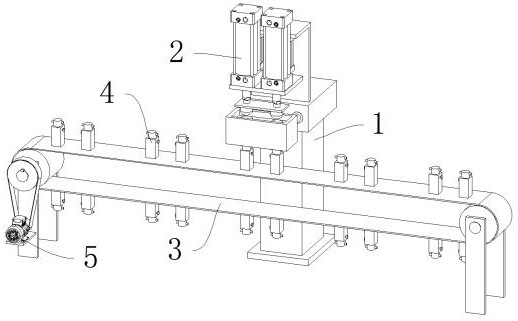
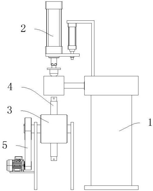
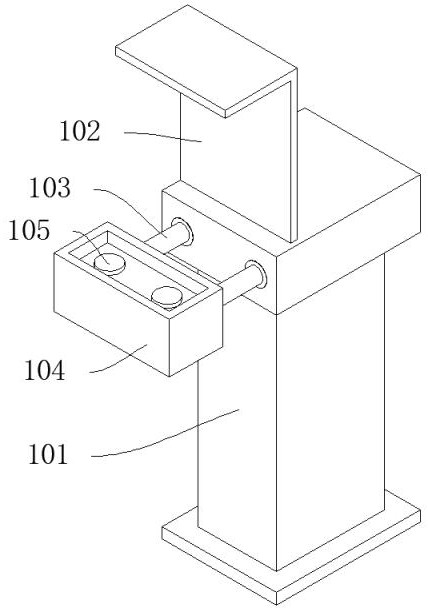
[0044] like Figure 1-Figure 7As shown, a printing equipment for processing PE bottle caps of different sizes, including a table device 1 for supporting printing, a pad printing device 2 for lifting printing is installed in front of the table device 1, and a pad printing device 2 is installed below the pad printing device 2 There is a conveying device 3 for conveying PE bottle caps, a number of positioning devices 4 for fixing PE bottle caps are evenly distributed on the conveying device 3, and a driving device 5 for providing power is installed in front of the conveying device 3; the table device 1 includes A support platform 101, a first support plate 102 is arranged on the support platform 101, two first cylinders 103 are symmetrically installed in the support platform 101, an ink cartridge 104 is installed in front of the first cylinder 103, and a pad printing plate 105 is installed in the ink cartridge 104 The pad printing device 2 includes 2 second cylinders 201 that are...

Embodiment 2

[0047] like Figure 8 As shown, the difference between Embodiment 2 and Embodiment 1 is that: the driving device 5 includes a motor 501, a pinion 505 is installed behind the motor 501, a bull gear 506 is arranged above the pinion 505, and the pinion 505 and the bull gear 506 are meshed for transmission; The motor 501 is connected with the motor base 302 by bolts, the motor 501 is connected with the pinion 505 by a flat key, and the bull gear 506 is connected with the transmission shaft 303 by a flat key.

[0048] Working principle: By rotating the support column 403 to lift up and down in the support block 401, the inclined cone 402 pushes the sliding rod 405 to stretch out the support column 403 under the support of the spring 406 to adjust the width, suitable for fixing PE bottle caps of different sizes, and the motor 501 drives the small belt The wheel 502 drives the large pulley 504 to rotate through the transmission belt 503, and the large pulley 504 drives the conveying ...


PUM


Abstract

The invention discloses printing equipment capable of conveniently machining PE bottle caps of different sizes. The printing equipment comprises a table device used for supporting printing. A transferprinting device used for ascending and descending to achieve printing is mounted on the front portion of the table device. A conveying device used for conveying PE bottle caps is arranged below the transfer printing device. Multiple locating devices used for fixing PE bottle caps are evenly distributed on the upper portion of the conveying device. A drive device used for providing power is mounted on the front portion of the conveying device. Through the arrangement of rotating of the locating devices, the clamping width can be adjusted conveniently so as to be suitable for machining PE bottle caps of different sizes; through the arrangement of the transfer printing device, transfer printing plates can be conveniently replaced to convert printing forms; and through the arrangement that PEbottle caps of different sizes are clamped by the locating devices, repeated replacement of clamps is avoided, and time and labor are saved.

Description

technical field [0001] The invention relates to the technical field of PE bottle cap printing, in particular to a printing device for processing PE bottle caps of different sizes. Background technique [0002] PE plastic refers to polyethylene, which is a thermoplastic resin obtained by polymerization of ethylene. Polyethylene is odorless, non-toxic, feels like wax, has excellent low temperature resistance, good chemical stability, and can withstand most acids and alkalis. Insoluble in common solvents at room temperature, low water absorption, excellent electrical insulation. So now more and more PE plastics are used in the production and packaging of bottled beverages, including PE bottle bodies and PE bottle caps. [0003] However, in the current technology, for the processing and printing of PE bottle caps of different sizes, different included angles need to be replaced, resulting in: 1. It is not convenient to adjust the clamping width to be suitable for processing PE...

Claims


Application Information

Patent Timeline
Patent Type & Authority Applications(China)
IPC IPC(8): B41F17/00
CPCB41F17/001
Inventor 吕涛
Owner 衡阳中豪科技有限公司
Why Eureka
Try Eureka