
Monitoring of MEMS mirror properties

A characteristic, nonlinear resonance technology used in the field of MEMS oscillatory systems to solve problems such as mismatches, laser shooting/printing errors, etc.

Active Publication Date: 2020-05-01
INFINEON TECH AG
View PDF7 Cites 3 Cited by
  • Summary
  • Abstract
  • Description
  • Claims
  • Application Information

AI Technical Summary

Problems solved by technology

These errors can cause considerable laser shooting / printing errors
For example, these issues can cause a mismatch between the desired mirror position and the measured position

Method used


Image

  • Monitoring of MEMS mirror properties
  • Monitoring of MEMS mirror properties
  • Monitoring of MEMS mirror properties

Examples


Embodiment Construction

[0018] Hereinafter, various embodiments will be described in detail with reference to the accompanying drawings. It should be noted that these examples are for illustrative purposes only and should not be construed as limiting. For example, although an embodiment may be described as including several features or elements, this should not be interpreted as indicating that all such features or elements are required to practice the embodiment. Conversely, in other embodiments, some features or elements may be omitted, or may be substituted for alternative features or elements. Furthermore, other features or elements than those explicitly shown and described may be provided, for example conventional components of a sensor device.

[0019] Unless specifically stated otherwise, features from different embodiments may be combined to form other embodiments. Variations or modifications described with respect to one of the embodiments may also be applicable to the other embodiments. ...


PUM


Abstract

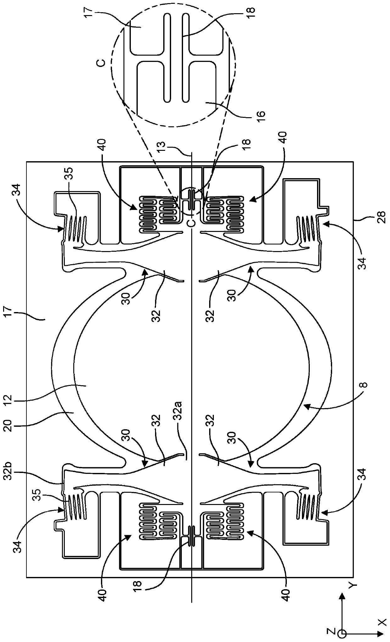
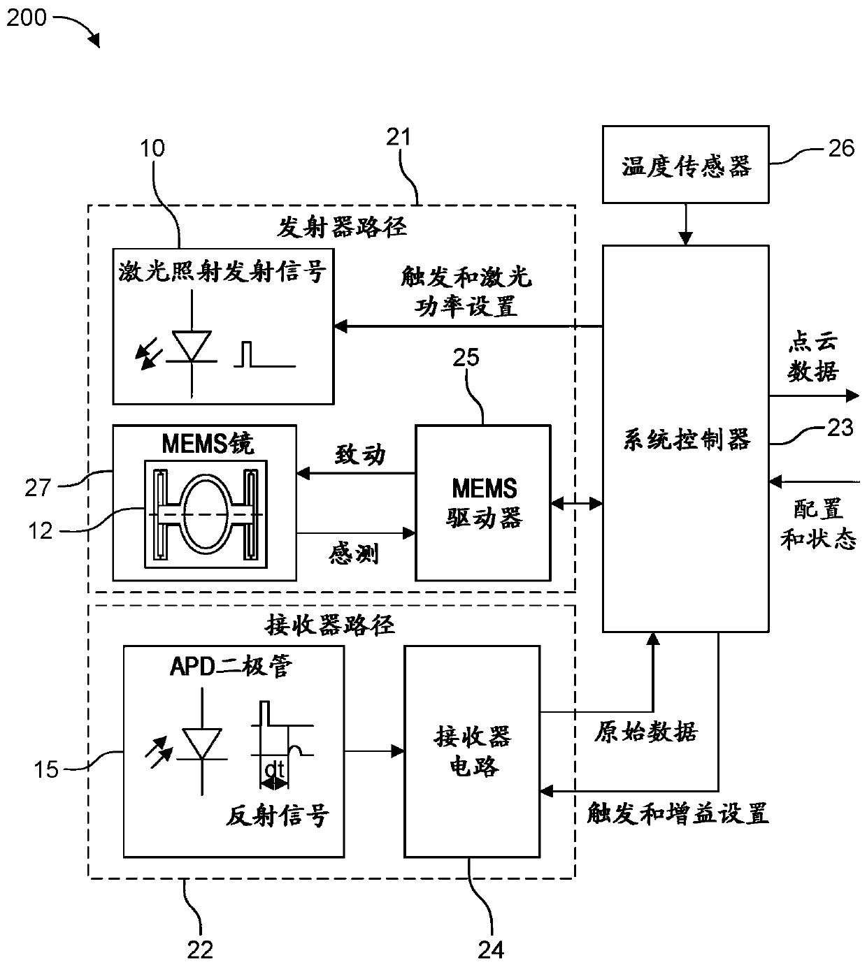
The disclosure relates to monitoring of MEMS mirror properties. Systems and methods are provided for monitoring properties of a microelectromechanical systems (MEMS) oscillating structure. A system includes a MEMS oscillating structure configured as a non-linear resonator to oscillate about a rotation axis; a driver configured to generate a driving force for driving the MEMS oscillating structureabout the rotation axis according to an operating response curve during which the MEMS oscillating structure is in resonance, the driver further configured to decrease the driving force when the MEMSoscillating structure is at a predefined tilt angle to induce an oscillation decay of the MEMS oscillating structure; a measurement circuit configured to measure an oscillation frequency and a tilt angle amplitude of the MEMS oscillating structure during a decay period; and processing circuitry configured to determine at least one characteristic of the MEMS oscillating structure based on at leastone of the measured oscillation frequency and the measured tilt angle amplitude.

Description

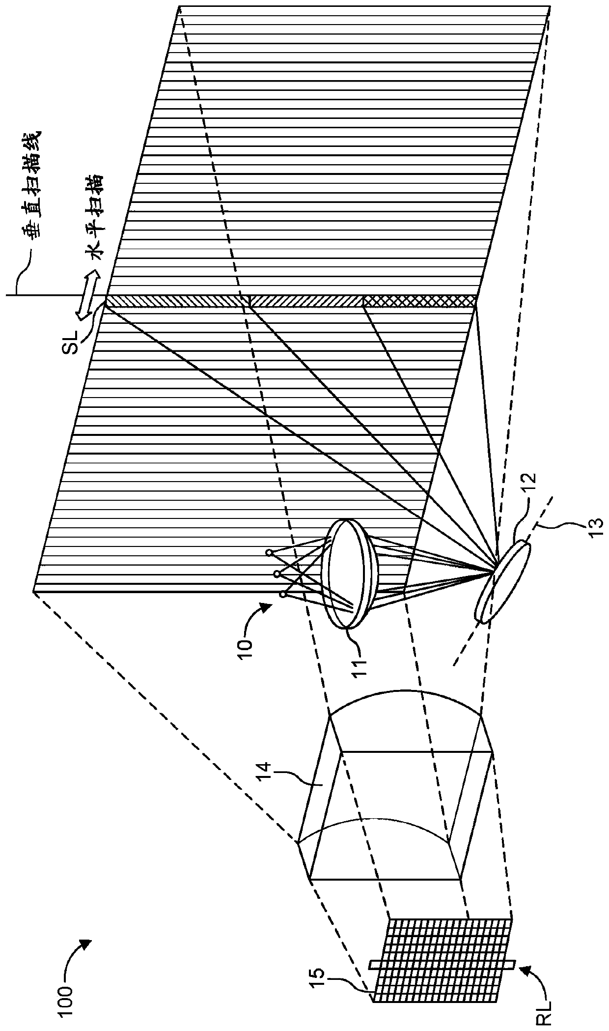
technical field [0001] The present disclosure relates generally to microelectromechanical systems (MEMS) oscillating systems and methods of operation thereof, and more particularly, to monitoring MEMS mirror characteristics. Background technique [0002] Lidar (LIDAR) is a long-range sensing method that uses light in the form of pulsed laser light to measure the distance (variable distance) to one or more objects in the field of view. Specifically, microelectromechanical system (MEMS) mirrors are used to scan the light across the field of view. An array of photodetectors receives reflections from objects illuminated by light and determines the time it takes for the reflections to reach each sensor in the photodetector array. This is also known as measuring time of flight (TOF). The LIDAR system forms depth measurements, and distance measurements are made by mapping distances to objects based on time-of-flight calculations. Thus, time-of-flight calculations can create dist...

Claims


Application Information

Patent Timeline
Patent Type & Authority Applications(China)
IPC IPC(8): G01S7/497G01S7/481
CPCG01S7/497G01S7/481G01S7/4817G01S7/4865G01S7/4815G01S17/894G01S7/4813G01S7/4863G02B26/0833G01N21/95G02B6/3584G02B6/3514G02B6/3518G01N21/55
Inventor H·范利罗普A·赫尔斯科J·维赫根
Owner INFINEON TECH AG
Learn More