Heat pump comprising a cooling device for cooling a guide space or a suction mouth

A technology of cooling equipment and suction port, which is applied in the field of heat pumps with cooling equipment for cooling the guide cavity or suction port, can solve the problems of small space, condenser size design restrictions, etc., achieve reliable operation of heat pumps, eliminate safety problems and corrosion problems, the effect of a reliable and stable heat pump

Active Publication Date: 2020-05-01
EFFICIENT ENERGY GMBH
View PDF9 Cites 0 Cited by
  • Summary
  • Abstract
  • Description
  • Claims
  • Application Information

AI Technical Summary

Problems solved by technology

Furthermore, the heat pump should occupy as little space as possible, which brings constraints on the dimensioning of the condenser

Method used


Image

  • Heat pump comprising a cooling device for cooling a guide space or a suction mouth
  • Heat pump comprising a cooling device for cooling a guide space or a suction mouth
  • Heat pump comprising a cooling device for cooling a guide space or a suction mouth

Examples


Embodiment Construction

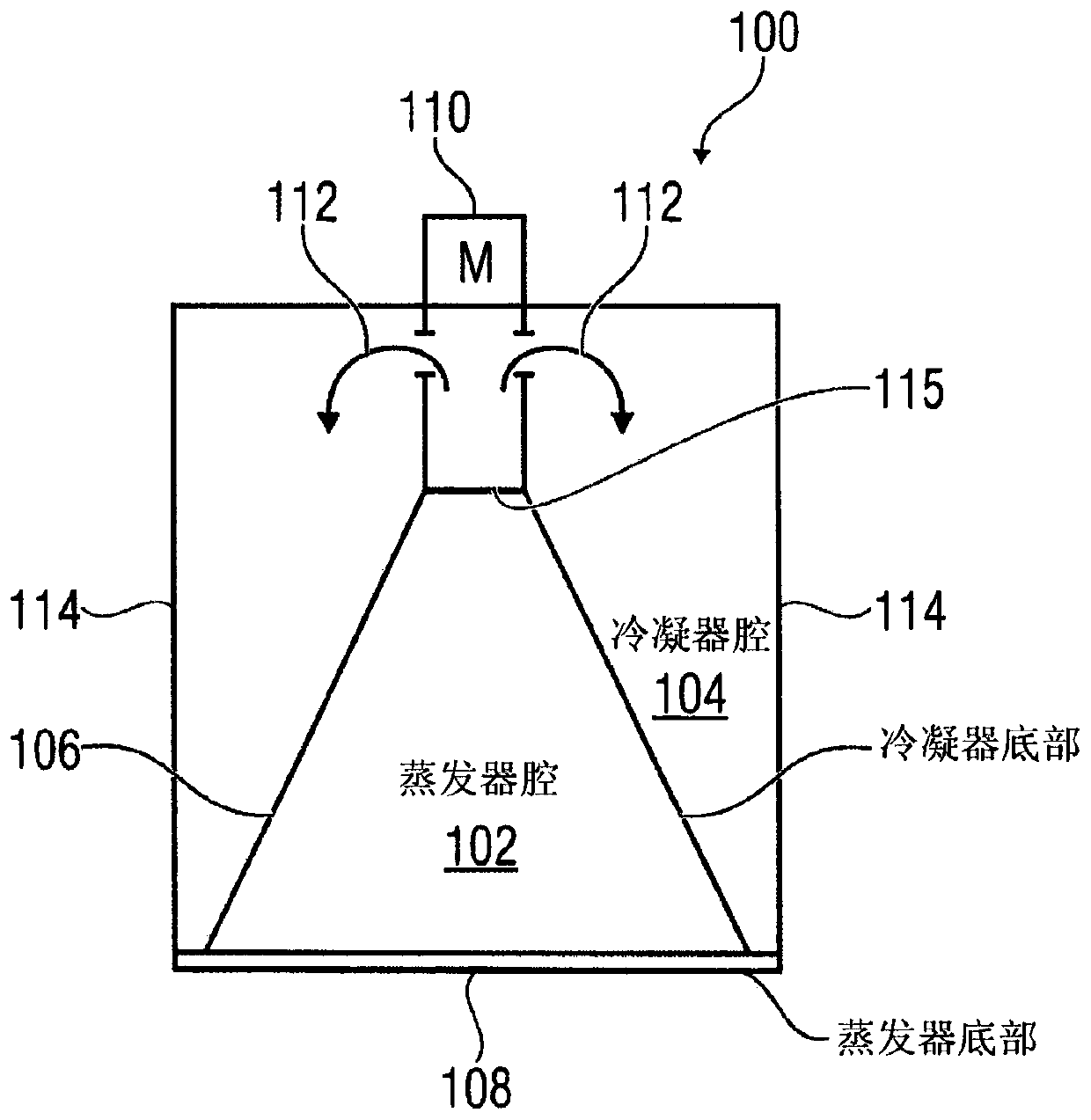
[0045] figure 1 Shown is a heat pump 100 having an evaporator for evaporating a working fluid in an evaporator chamber 102 . The heat pump also includes a condenser for liquefying evaporated working liquid in a condenser chamber 104 delimited by a condenser bottom 106 . as visible as a sectional view or as a side view figure 1 As shown, the evaporator cavity 102 is at least partially surrounded by the condenser cavity 104 . Furthermore, the evaporator chamber 102 is separated from the condenser chamber 104 by a condenser bottom 106 . Furthermore, the condenser bottom is connected to the evaporator bottom 108 so as to define the evaporator cavity 102 . In one implementation, a compressor 110 is located above the evaporator chamber 102 or at another location, the compressor at figure 1 Although not shown in detail, the compressor is designed in principle to compress the evaporated working fluid and to conduct it as compressed vapor 112 into the condenser space 104 . The con...


PUM


Abstract

The invention relates to a heat pump having the following features: an evaporator (90) for evaporating working liquid; a condenser (114) for condensing compressed working steam; a compressor motor (110) having a suction mouth (92), on which a radial impeller (304) is mounted in order to convey working steam (314) evaporated in the evaporator (90) through the suction mouth (92); a guide space (302)which is arranged to guide a working steam (112) conveyed by the radial impeller (304) into the condenser (114); and a cooling device (420) for cooling the guide space (302) or the suction mouth (92)with a liquid, wherein the cooling device (420) is designed to guide (421, 422) the liquid on an outer side of the guide space (302) or the suction mouth (92), wherein the outer side is not in contact with the working steam (314, 112), and wherein an inner side of the guide space (302) or the suction mouth (92) is in contact with the working steam (314, 112).

Description

Background technique [0001] Figures 8A and 8B show a heat pump as described in European patent EP 2016349 B1. The heat pump firstly comprises an evaporator 10 for evaporating water as working fluid in order to generate steam on the output side in a working steam line 12 . The evaporator includes an evaporating chamber (not shown in FIG. 8A ) and is configured to generate an evaporating pressure of less than 20 hPa in the evaporating chamber, so that water evaporates in the evaporating chamber at a temperature of less than 15° C. The water is for example ground water, using brine which circulates freely in the soil or in collecting pipes, ie water with a specific salt content, river water, lake water or sea water. All types of water can be used i.e. calcium water, calcium free water, saline or non-salt water. This consists in the fact that all types of water, ie all said "water substances" with favorable water properties, ie water also known as "R718", have an enthalpy differ...

Claims


Application Information

Patent Timeline
Patent Type & Authority Applications(China)
IPC IPC(8): F25B30/02F25B31/00F25B31/02
CPCF25B30/02F25B31/008F25B31/026F25B2400/071F25B31/006F25B2500/09
Inventor 奥利弗·克尼夫勒
Owner EFFICIENT ENERGY GMBH
Why Eureka
Try Eureka