
Cooling plasma cutting systems and related systems and methods

A cutting system, plasma technology, applied in the direction of plasma, plasma welding equipment, modification of power electronics, etc., can solve the problems of system inefficiency, component/system failure, etc., and achieve the effect of efficient cooling

Active Publication Date: 2019-04-16
HYPERTHERM INC
View PDF9 Cites 0 Cited by
  • Summary
  • Abstract
  • Description
  • Claims
  • Application Information

AI Technical Summary

Problems solved by technology

This heat can lead to system inefficiencies and even component / system failures

Method used


Image

  • Cooling plasma cutting systems and related systems and methods
  • Cooling plasma cutting systems and related systems and methods
  • Cooling plasma cutting systems and related systems and methods

Examples


Embodiment Construction

[0029] In some aspects, a plasma arc power supply may include multiple cooling circuits that each house sets of different types of components that may have different operating characteristics and cooling requirements. As such, different cooling circuits may be configured to provide different cooling flows so that different components may be cooled at different (eg, tailored) cooling rates.

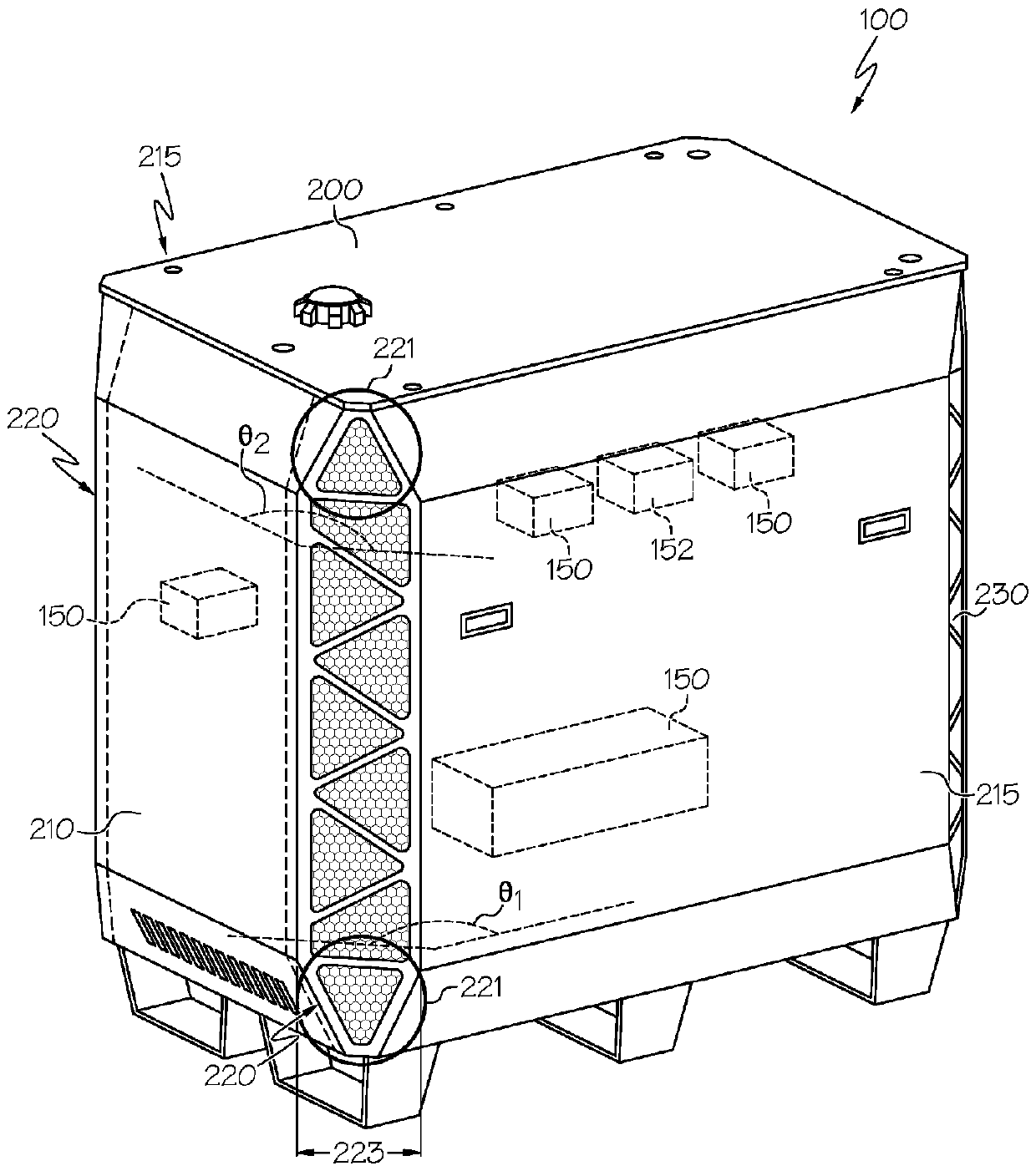
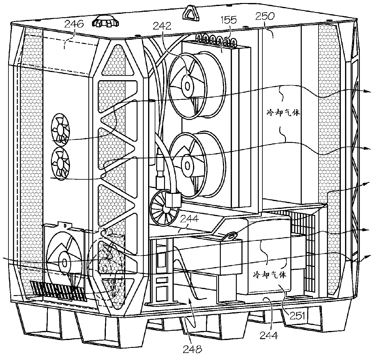
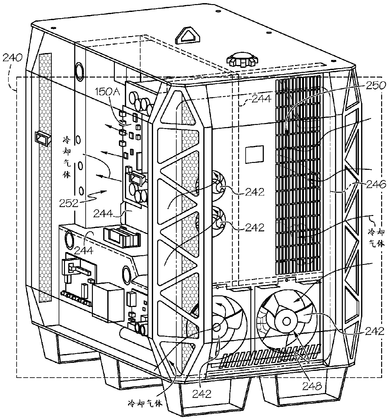
[0030] For example, refer to figure 1 A power supply 100 for a plasma cutting system (eg, a liquid cooled or robotic plasma cutting system) may be configured to support the generation of a plasma arc through a torch tip connected to the power supply by a torch lead. The power supply 100 may include a set of electrical components 150 for plasma arc generation and a power supply housing 200 housing the set of electrical components 150 . Power supply 100 may include a liquid coolant system disposed within housing 200 (in image 3 Shown in cross-sectional view as system 155), the liquid cool...


PUM


Abstract

In some aspects, power supplies for liquid cooled plasma cutting systems configured to support plasma arc generation by a torch head connected to the power supply can include: a set of electrical components for plasma arc generation; and a power supply housing containing the set of electrical components, the power supply housing having a front panel and at least two side panels and defining: a setof inlets for allowing a cooling gas to enter the power supply housing to thermally regulate the set of electrical components, at least one inlet of the set of inlets being positioned at a corner ofthe housing and oriented at a non-zero angle relative to the front panel and to at least one of the two side panels; and a set of vents for allowing at least a portion of the cooling gas to exit the power supply housing.

Description

[0001] related application [0002] This application claims the benefit of U.S. Provisional Patent Application Serial No. 62 / 330387, entitled "Gas Circulation for a Plasma Arc Cutting System," filed May 2, 2016, the contents of which are hereby incorporated by reference in its entirety incorporated herein in its entirety. technical field [0003] The present disclosure relates generally to plasma cutting systems, and more particularly to cooling plasma cutting systems and related systems and methods. Background technique [0004] Plasma arc cutting torches are widely used for cutting, gouging and marking materials. Plasma arc torches typically include an electrode, a nozzle with a central exit orifice mounted within the torch body, electrical connections, passages for cooling, and passages for an arc control fluid (eg, plasma gas). Optionally, a swirl ring is used to control the fluid flow pattern in the plasma chamber formed between the electrode and the nozzle. In some ...

Claims


Application Information

Patent Timeline
IPC IPC(8): H05H1/36B23K9/10B23K10/00H05K7/20
CPCB23K9/1006B23K10/006H05H1/36H05H1/28H05K7/20909B23K10/00B23K37/003H05K5/0213H05K5/03
Inventor B.米柳斯B.J.柯里尔G.R.卡马思
Owner HYPERTHERM INC
Learn More