Detachable CFG pile drilling device

A drilling device and detachable technology, applied in the field of detachable CFG pile drilling devices, can solve the problems of troublesome connection of drill pipes, inconvenient use, waste of time, etc., and achieve the effect of improving efficiency

Inactive Publication Date: 2020-05-05
深圳市河图建设项目管理有限公司
View PDF1 Cites 2 Cited by
  • Summary
  • Abstract
  • Description
  • Claims
  • Application Information

AI Technical Summary

Problems solved by technology

A low-clearance CFG pile drill pipe in the above-mentioned patent has the following disadvantages: two drill pipe joints are connected by thread fit, and it is troublesome to connect the drill pipes, a lot of time will be wasted, and it is inconvenient to use

Method used


Image

  • Detachable CFG pile drilling device
  • Detachable CFG pile drilling device
  • Detachable CFG pile drilling device

Examples


Embodiment 1

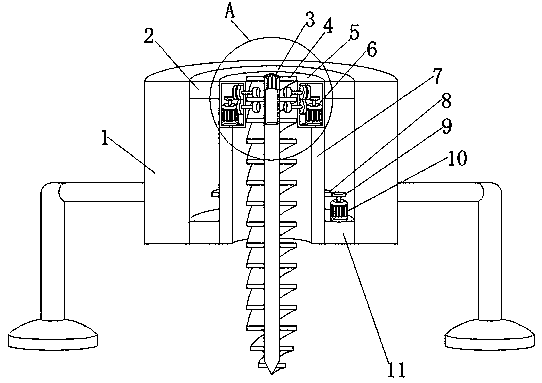
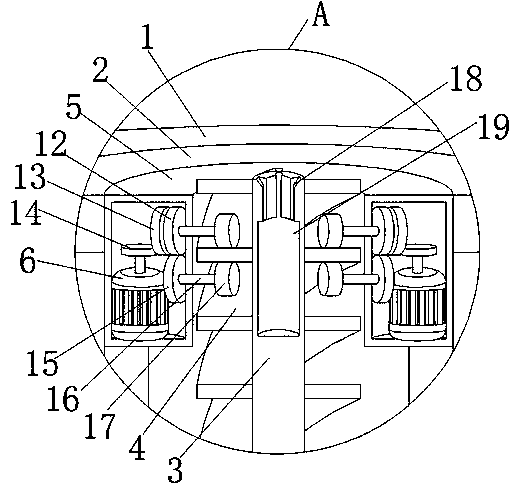
[0028] refer to Figure 1-5 , a detachable CFG pile drilling device, comprising a main body 1, a first drill rod 3 and a second drill rod 20, the middle part of the main body 1 is provided with a first through hole, and the main body 1 is welded with a second through hole at the first through hole A fixed ring 2 and a second fixed ring 11, the middle part of the second fixed ring 11 is rotatably connected with a rotating body 7, the top of the rotating body 7 is welded with a fixed box 5, the inside of the fixed box 5 is provided with a drive mechanism, and the fixed box 5 is ring, the first drill rod 3 is in the middle of the fixed box 5, and the inner walls on both sides of the fixed box 5 are rotatably connected with two rotating shafts 16, and one end of the two rotating shafts 16 is connected with a roller 17 by a key, and the first drill rod 3 and the outer wall of the second drill rod 20 are welded with a helical piece 4, the helical piece 4 is between the two rollers 1...

Embodiment 2

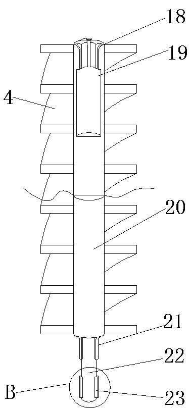
[0037] refer to Image 6 , a detachable CFG pile drilling device. Compared with Embodiment 1, in order to increase the practicability of the device and facilitate the disassembly of the second drill rod 20, the top of the main body 1 is welded with two support columns 26, The tops of the two support columns 26 are welded with the same fixed body 27, and the middle part of the fixed body 27 is provided with an electromagnetic chuck 28. When the drilling is completed and the second drilling rod 20 rises, the second drilling 20 is separated from the roller 17. Start the electromagnetic chuck 28 at the same time, the electromagnetic chuck 28 produces suction, attracts the second drill rod 20, makes the upper body of the second drill rod 20, the block 21 is separated from the draw-in groove 18, the first drill rod 3 cannot drive the second drill rod 20 to rotate, Under the action of the spring 25, the two moving blocks 23 return to their original positions, the fixing rod 22 can le...


PUM


Abstract

The invention belongs to the technical field of building equipment, particularly relates to a detachable CFG pile drilling device. In order to solve the problem that a CFG pile drill rod with the toolong length is relatively inconvenient to use, the following scheme is provided presently. According to the scheme, the detachable CFG pile drilling device comprises a main body, a first drill rod anda second drill rod, a first through hole is formed in the middle of the main body, the main body is provided with a first fixing ring and a second fixing ring at the first through hole in a welded mode, a rotating body is rotationally connected to the middle of the second fixing ring, a fixing box is welded to the top end of the rotating body, a driving mechanism is arranged inside the fixing box, the fixing box is annular, and the first drill rod is located in the middle of the fixing box. According to the detachable CFG pile drilling device, rollers, spiral pieces, the first drill rod and the second drill rod are arranged, the driving mechanism enables the two rollers to drive the first drill rod to rotate and descend through the spiral pieces, then a fixing rod at the bottom end of thesecond drill rod is inserted into the first drill rod, so that the first drill rod is connected with the second drill rod, the second drill rod is continuously added so that the drilling depth can becontinuously increased.

Description

technical field [0001] The invention relates to the technical field of construction equipment, in particular to a detachable CFG pile drilling device. Background technique [0002] CFG pile is the abbreviation of cement fly ash gravel pile, which is widely used in the field of construction. One is to drill holes through drill pipes, and then add materials. When drilling, longer drill pipes will be used to make the depth of the hole It meets the requirements, but the drill pipe with too long length is inconvenient to use, especially when there are cables, bridges and other buildings that will occupy space above the construction site. [0003] After retrieval, the Chinese patent application number is CN201820742124.0, which discloses a low-clearance CFG pile drill pipe. The drill pipe includes a CFG drill pipe body, and the CFG drill pipe body includes a multi-section drill pipe section. For splicing, the outer wall of the lower part of the drill pipe section is provided with...

Claims


Application Information

Patent Timeline
Patent Type & Authority Applications(China)
IPC IPC(8): B28D1/14B28D7/00B28D7/04
CPCB28D1/14B28D7/00B28D7/046
Inventor 李超柳晓云柳泽滨张世杰陈俊君刘钦杰
Owner 深圳市河图建设项目管理有限公司
Why Eureka
Try Eureka