Composite material car body, composite material layup structure and layup method

A composite material and lay-up technology, applied in the direction of railway car bodies, superstructures, railway car body parts, etc., can solve the problems of mechanical performance reduction and achieve the effect of solving the reduction of mechanical properties

Active Publication Date: 2021-08-06
CRRC QINGDAO SIFANG CO LTD
View PDF10 Cites 0 Cited by
  • Summary
  • Abstract
  • Description
  • Claims
  • Application Information

AI Technical Summary

Problems solved by technology

[0005] The purpose of the present invention is to provide a composite material layup structure, which adopts the layup structure of composite material profiles and the cladding form of butt joints to solve the problem caused by the butt joint of multiaxial cloth in the vertical pultrusion direction of composite material pultruded profiles with complex sections. The problem of reduced mechanical properties

Method used


Image

  • Composite material car body, composite material layup structure and layup method
  • Composite material car body, composite material layup structure and layup method

Examples


Embodiment Construction

[0026] The following will clearly and completely describe the technical solutions in the embodiments of the present invention with reference to the accompanying drawings in the embodiments of the present invention. Obviously, the described embodiments are only some, not all, embodiments of the present invention. Based on the embodiments of the present invention, all other embodiments obtained by persons of ordinary skill in the art without making creative efforts belong to the protection scope of the present invention.

[0027] In order to enable those skilled in the art to better understand the solution of the present invention, the present invention will be further described in detail below in conjunction with the accompanying drawings and specific embodiments.

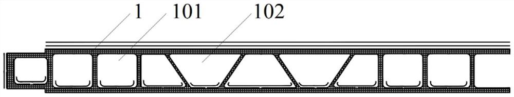
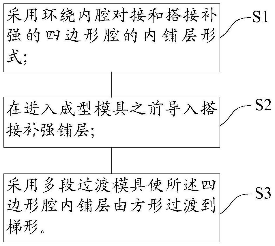
[0028] Please refer to figure 1 and figure 2 ,in, figure 1 Schematic diagram of the structure of the composite material lay-up structure provided by the embodiment of the present invention, figure 2 It is a sch...


PUM


Abstract

The invention discloses a composite material lay-up structure, which comprises a profile provided with a plurality of quadrilateral cavities which are butt-connected and then reinforced by overlapping. The quadrilateral cavity includes a square cavity and a mold cavity. Trapezoidal shape transition. The invention also discloses a composite material vehicle body. The invention also discloses a composite material laying method. The above-mentioned composite material lay-up structure adopts the lay-up structure of composite material profiles and the cladding form of butt joints, which solves the problem of the reduction of mechanical properties caused by the butt joint of multi-axis cloth in the vertical direction of pultrusion of composite material pultruded profiles with complex sections.

Description

technical field [0001] The invention relates to the technical field of composite material layup, in particular to a composite material vehicle body. In particular, it relates to a composite layup structure. It also relates to a composite material laying method. Background technique [0002] Composite car body or skirt panel structure mostly adopts sandwich panel or winding forming structure, which cannot solve the problem of mechanical property reduction caused by multi-axis cloth butt joint in vertical pultrusion direction of composite pultruded profiles with complex cross-sections. [0003] In the first prior art, the load-bearing skeleton is made of fiber-reinforced resin-based composite material covering the foam core structure, the inner panel is made of fiber-reinforced resin-based composite material, and the part of the outer panel located on the inner surface is fiber-reinforced Resin-based composite materials; in the second prior art, the car body adopts a sandwic...

Claims


Application Information

Patent Timeline
Patent Type & Authority Patents(China)
IPC IPC(8): B62D29/04B61D17/00B29C70/32
CPCB62D29/043B61D17/00B29C70/32B61D17/005B29C70/16B29D99/0017B29C70/30B29K2105/0845B29K2307/04B62D25/00
Inventor 丁叁叁肖鹏高玉龙赵红伟吴沛沛
Owner CRRC QINGDAO SIFANG CO LTD
Why Eureka
Try Eureka